PRODUCT DESCRIPTION & TECHNICAL DOCUMENTS
How sewage treatment plant – mbr fits your process.
Operating principle
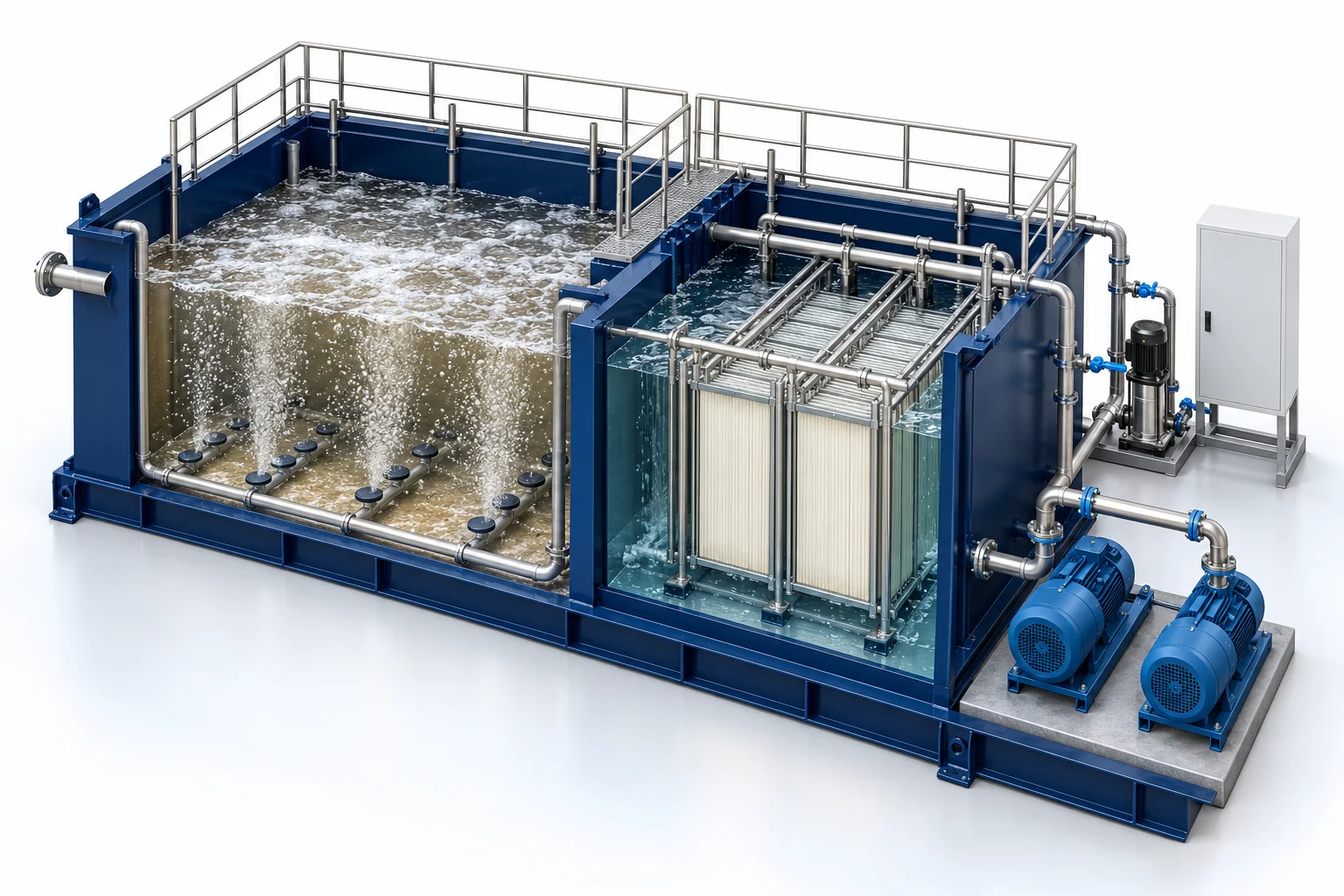
Biological sewage treatment combined with membrane separation of treated water and biomass.
Biological treatment uses a controlled microbial process to reduce biodegradable pollution. MBBR, MBR, SBR and ASP use different biomass-retention and solids-separation arrangements.
Engineering checks
- Inflow profile, BOD, COD, TSS and nutrients
- Biodegradability and inhibition risks
- Hydraulic and organic loading
- Oxygen transfer, solids handling and reuse objective
Configuration & equipment
- Inlet screening and equalization interface
- Selected biological reactor
- Aeration and mixing equipment
- Biomass retention / separation stage
- Sludge withdrawal and handling
- Treated-water polishing as required
- Monitoring, controls and sampling
Configuration options are reviewed against the project duty. Supply quantities and final scope are defined in the approved proposal.
| Process / operating item | Engineering requirement |
|---|---|
| Process review 1 | Membranes retain biomass; a secondary settling tank is not part of this indicative route. |
| Process review 2 | Aeration, membrane cleaning and sludge wasting are part of detailed system design. |
| Operating and maintenance | Trend process water quality and biomass condition. Inspect aeration distribution and mechanical equipment. Maintain a defined sludge-wasting and sampling routine. |
| Documentation | Project-specific datasheet, PFD, P&ID, equipment GA, electrical load list and O&M documentation as agreed. |
PDF & DRAWING DOWNLOADS
Keep the technical references.
Read the wastewater treatment brochure, or download the process and arrangement drawings below.
PROCESS FLOW DIAGRAM
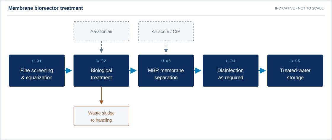
Membrane bioreactor treatment
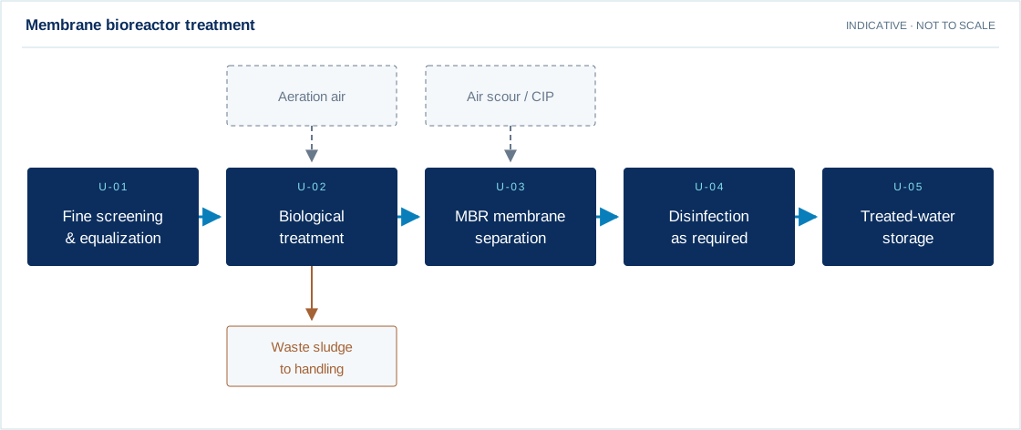
Swipe the diagram to view every stage.
- Membranes retain biomass; a secondary settling tank is not part of this indicative route.
- Aeration, membrane cleaning and sludge wasting are part of detailed system design.
Indicative process overview. Equipment tags identify functional blocks only. Final PFDs, P&IDs, duties, sizes, valves and instruments are developed from the approved project design basis.
EQUIPMENT DRAWINGS
2D layout & exploded component views.
Review the functional arrangement and the components that make up the equipment.


EXPLODED VIEW
Understand the assembly.
The separated component schematic identifies the main equipment groups. Vendor-specific internal geometry is established during detailed engineering.
- Inlet screening and equalization interface
- Selected biological reactor
- Aeration and mixing equipment
- Biomass retention / separation stage
- Sludge withdrawal and handling
- Treated-water polishing as required
- Monitoring, controls and sampling