Bakrol, Ahmedabad, India+91 97277 86892

Wastewater treatment

Sewage Treatment Plant – ASP

Suspended-growth biological sewage treatment with clarification and sludge recycle.

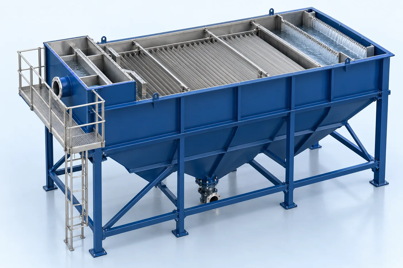
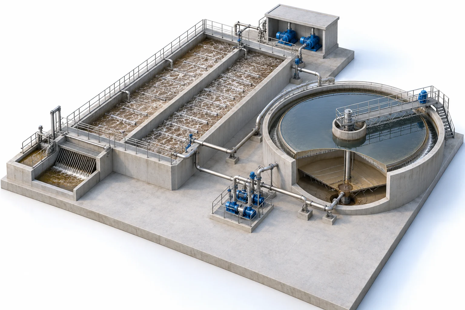
Conceptual 3D visualization of civil activated-sludge plant
Civil activated-sludge plant — conceptual equipment visualization; final configuration follows approved design.

3D EQUIPMENT VIEW

Sewage Treatment Plant – ASP

Explore the equipment arrangement, then read how the system works and review its technical drawings.

Description & drawings Browse equipment renders

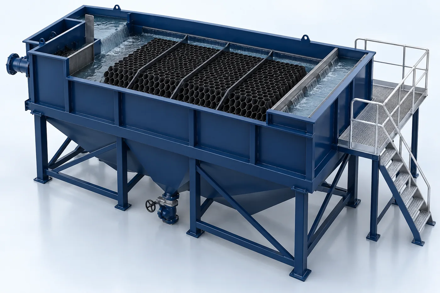
Conceptual equipment render. Final dimensions and configuration follow the approved project design.

PRODUCT DESCRIPTION & TECHNICAL DOCUMENTS

How sewage treatment plant – asp fits your process.

Operating principle

Suspended-growth biological sewage treatment with clarification and sludge recycle.

Biological treatment uses a controlled microbial process to reduce biodegradable pollution. MBBR, MBR, SBR and ASP use different biomass-retention and solids-separation arrangements.

Engineering checks

  • Inflow profile, BOD, COD, TSS and nutrients
  • Biodegradability and inhibition risks
  • Hydraulic and organic loading
  • Oxygen transfer, solids handling and reuse objective

Configuration & equipment

  1. Inlet screening and equalization interface
  2. Selected biological reactor
  3. Aeration and mixing equipment
  4. Biomass retention / separation stage
  5. Sludge withdrawal and handling
  6. Treated-water polishing as required
  7. Monitoring, controls and sampling

Configuration options are reviewed against the project duty. Supply quantities and final scope are defined in the approved proposal.

Process / operating itemEngineering requirement
Process review 1Return activated sludge maintains biomass in the aeration system.
Process review 2Waste sludge is removed separately for solids handling.
Operating and maintenanceTrend process water quality and biomass condition. Inspect aeration distribution and mechanical equipment. Maintain a defined sludge-wasting and sampling routine.
DocumentationProject-specific datasheet, PFD, P&ID, equipment GA, electrical load list and O&M documentation as agreed.

PDF & DRAWING DOWNLOADS

Keep the technical references.

Read the wastewater treatment brochure, or download the process and arrangement drawings below.

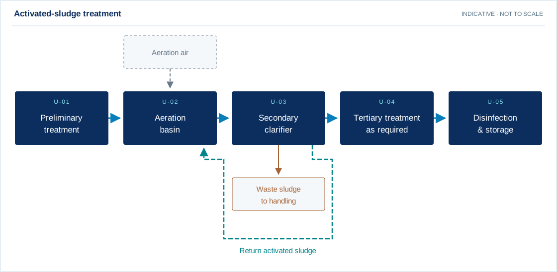
PROCESS FLOW DIAGRAM

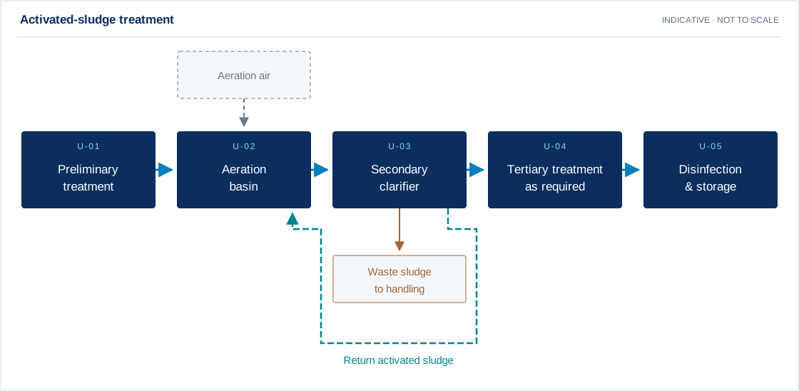
Activated-sludge treatment
Download drawing (SVG)
Preliminary treatment → Aeration basin → Secondary clarifier → Tertiary treatment as required → Disinfection & storage
Main process Utility / chemical Residual stream Recovery / recycle

Swipe the diagram to view every stage.

Design notes
  • Return activated sludge maintains biomass in the aeration system.
  • Waste sludge is removed separately for solids handling.

Indicative process overview. Equipment tags identify functional blocks only. Final PFDs, P&IDs, duties, sizes, valves and instruments are developed from the approved project design basis.

EQUIPMENT DRAWINGS

2D layout & exploded component views.

Sewage Treatment Plant – ASP 2D functional arrangement
Sewage Treatment Plant – ASP component decomposition reference
Sewage Treatment Plant – ASP — component decomposition

EXPLODED VIEW

Understand the assembly.

  1. Inlet screening and equalization interface
  2. Selected biological reactor
  3. Aeration and mixing equipment
  4. Biomass retention / separation stage
  5. Sludge withdrawal and handling
  6. Treated-water polishing as required
  7. Monitoring, controls and sampling

EXPLORE YOUR DESIGN BASIS

See how operating hours change energy use.

Enter the total running electrical load for this equipment or plant, then adjust its daily running hours.

Illustrative arithmetic using your inputs. These values are not measured plant results or a performance promise.

Daily electricity
80.00 kWh/day
30-day electricity
2400.00 kWh

Energy = electrical kW × running hours. Constant running load; standby load, starting transients and tariff charges are excluded.

Open detailed calculator →

CONSTRUCTION OPTIONS

Modular fabrication or civil construction?

Prefabricated modular plant

Factory-fabricated process modules connect to agreed site tanks and utilities. Review transport dimensions, lifting access, corrosion protection and maintenance clearances.

For a packaged MBBR example, the anoxic and aerobic compartments have flat floors; a downstream tube-settler compartment can use a sludge hopper. Equalization and treated-water storage may be separate civil tanks.

Explore modular STP / ETP →

Civil construction plant

Site-built basins provide a project-specific layout. Process design must coordinate with soil conditions, groundwater, structural design, hydraulic levels and access for operation.

RCC construction can support several treatment technologies. Civil scope, embedded items, tank lining and mechanical interfaces are defined before execution.

Explore civil STP / ETP →

YOUR PROJECT, YOUR DESIGN BASIS

Configure your requirement.

Enter what you know. Leave unavailable values blank for engineering review.

Process inputs

Daily sewage flow, operating pattern, population/source, BOD/COD/TSS, oil & grease if relevant, nitrogen targets, reuse/discharge objective, footprint, odour/noise and automation constraints.

Technologies you would like to discuss

Select candidates for review. This does not establish a treatment sequence.

Equipment & execution preferences

Materials are reviewed separately for each component against the fluid chemistry, temperature and service conditions. Preferences are subject to technical suitability and the agreed proposal.

No details are sent until you choose a sending channel.

A solution shaped by your requirements.

Suspended-growth biological sewage treatment with clarification and sludge recycle. Treatment begins with understanding the effluent sources and their variability. Physical, chemical and biological stages are combined as appropriate, followed by polishing and sludge management.

What we review

  • Average daily flow and hourly inflow profile
  • Operating hours and peak-flow conditions
  • BOD, COD, TSS, pH, nutrients and relevant contaminants
  • Reuse or discharge objective
  • Available area, levels and site interfaces
  • Treatability, sludge handling and odour constraints

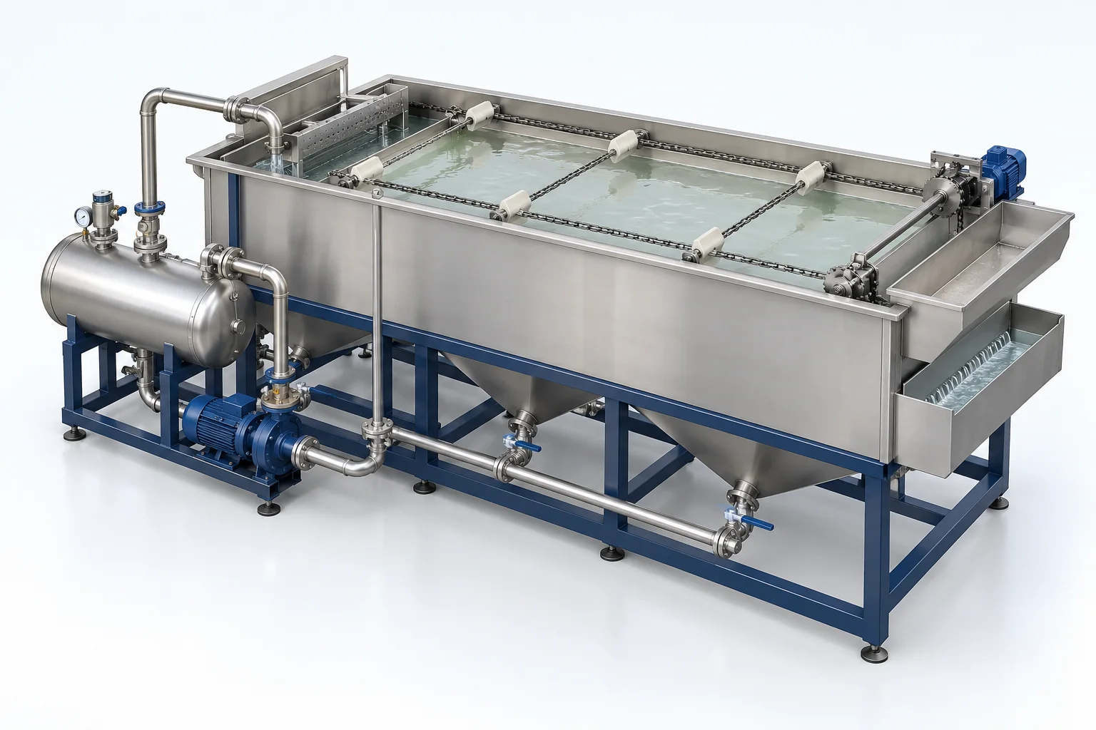
Capacity, materials, operating conditions and performance are specified after review of your project data. Product images are conceptual visualizations.

From design to operation

Our scope can cover process and mechanical engineering, manufacturing, supply, installation, commissioning and ongoing support. The final proposal clearly defines supplier scope, client interfaces, optional items and exclusions.

APPLICATIONS

Connect equipment to your industry.

Review the application, data requirements and candidate treatment options.