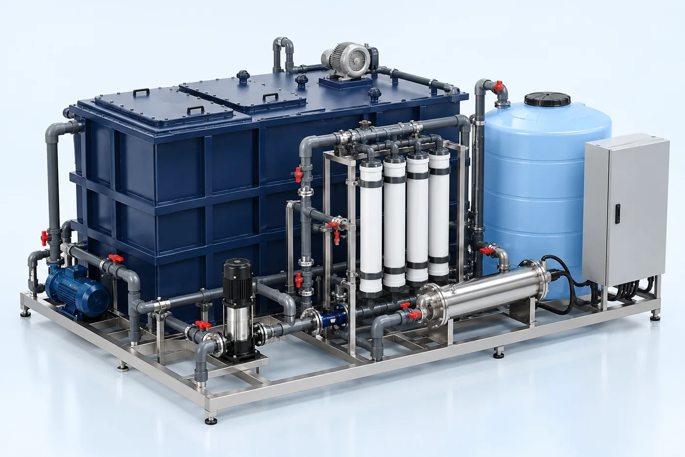
PRODUCT DESCRIPTION & TECHNICAL DOCUMENTS
How greywater recycling plant fits your process.
Operating principle
Treatment and reuse of segregated greywater for a defined non-potable application.
Biological treatment uses a controlled microbial process to reduce biodegradable pollution. MBBR, MBR, SBR and ASP use different biomass-retention and solids-separation arrangements.
Engineering checks
- Inflow profile, BOD, COD, TSS and nutrients
- Biodegradability and inhibition risks
- Hydraulic and organic loading
- Oxygen transfer, solids handling and reuse objective
Configuration & equipment
- Inlet screening and equalization interface
- Selected biological reactor
- Aeration and mixing equipment
- Biomass retention / separation stage
- Sludge withdrawal and handling
- Treated-water polishing as required
- Monitoring, controls and sampling
Configuration options are reviewed against the project duty. Supply quantities and final scope are defined in the approved proposal.
| Process / operating item | Engineering requirement |
|---|---|
| Process review 1 | MBR is one candidate route for greywater recycling; the final process follows analysis and the intended reuse. |
| Process review 2 | Membranes retain biomass; a secondary settling tank is not part of this indicative route. |
| Process review 3 | Aeration, membrane cleaning and sludge wasting are part of detailed system design. |
| Operating and maintenance | Trend process water quality and biomass condition. Inspect aeration distribution and mechanical equipment. Maintain a defined sludge-wasting and sampling routine. |
| Documentation | Project-specific datasheet, PFD, P&ID, equipment GA, electrical load list and O&M documentation as agreed. |
PDF & DRAWING DOWNLOADS
Keep the technical references.
Read the wastewater treatment brochure, or download the process and arrangement drawings below.
PROCESS FLOW DIAGRAM
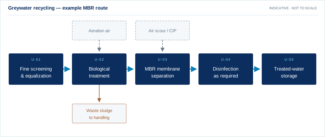
Greywater recycling — example MBR route
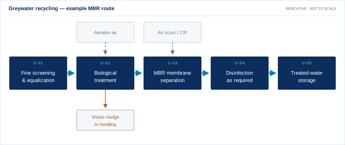
Swipe the diagram to view every stage.
- MBR is one candidate route for greywater recycling; the final process follows analysis and the intended reuse.
- Membranes retain biomass; a secondary settling tank is not part of this indicative route.
- Aeration, membrane cleaning and sludge wasting are part of detailed system design.
Indicative process overview. Equipment tags identify functional blocks only. Final PFDs, P&IDs, duties, sizes, valves and instruments are developed from the approved project design basis.
EQUIPMENT DRAWINGS
2D layout & exploded component views.
Review the functional arrangement and the components that make up the equipment.


EXPLODED VIEW
Understand the assembly.
The separated component schematic identifies the main equipment groups. Vendor-specific internal geometry is established during detailed engineering.
- Inlet screening and equalization interface
- Selected biological reactor
- Aeration and mixing equipment
- Biomass retention / separation stage
- Sludge withdrawal and handling
- Treated-water polishing as required
- Monitoring, controls and sampling