PRODUCT DESCRIPTION & TECHNICAL DOCUMENTS
How boiler feed water treatment fits your process.
Operating principle
Feed-water treatment configured around boiler operating requirements and source analysis.
Pressure drives water through a semipermeable membrane. The feed separates into permeate and a concentrate stream; recovery and membrane arrangement are established from water chemistry and a membrane projection.
Engineering checks
- Feed ionic analysis, temperature, SDI and turbidity
- Scaling potential at proposed recovery
- Element flux, crossflow and pressure limits
- Permeate quality and concentrate-management route
Configuration & equipment
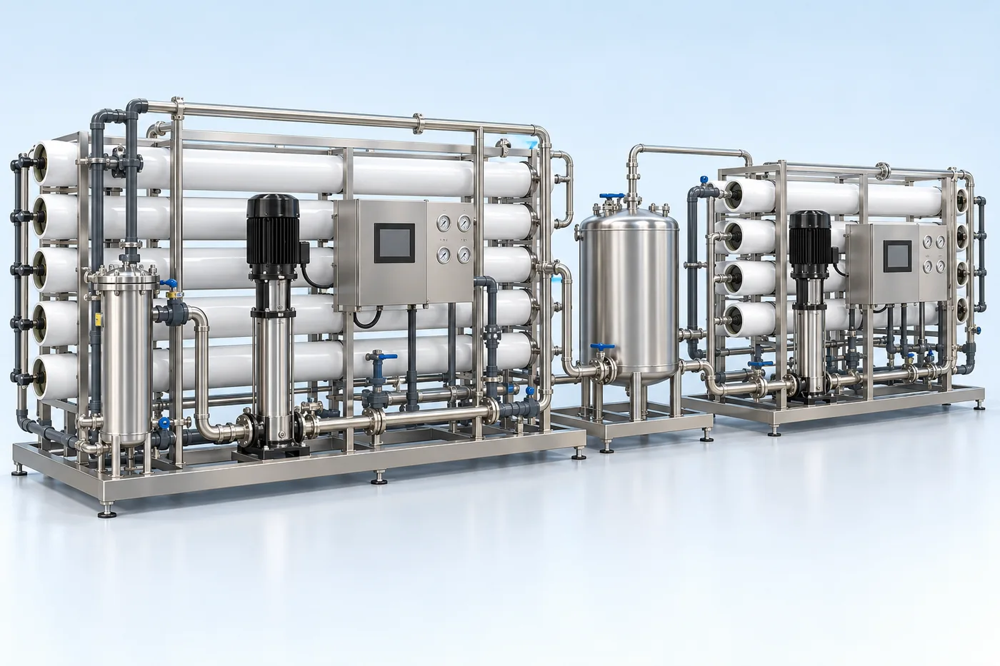
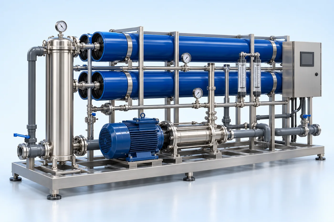
- Feed conditioning and cartridge filtration
- High-pressure feed pump
- Membrane pressure housings
- Spiral-wound membrane elements
- Permeate and concentrate manifolds
- Pressure, conductivity and flow instruments
- Cleaning connections and control panel
Configuration options are reviewed against the project duty. Supply quantities and final scope are defined in the approved proposal.
| Process / operating item | Engineering requirement |
|---|---|
| Process review 1 | The treatment combination is established from source-water analysis and the final use specification. |
| Operating and maintenance | Trend normalized permeate flow and salt passage. Inspect differential pressure and cartridge loading. Use approved cleaning chemistry and membrane preservation. |
| Documentation | Project-specific datasheet, PFD, P&ID, equipment GA, electrical load list and O&M documentation as agreed. |
PDF & DRAWING DOWNLOADS
Keep the technical references.
Read the water treatment & ro brochure, or download the process and arrangement drawings below.
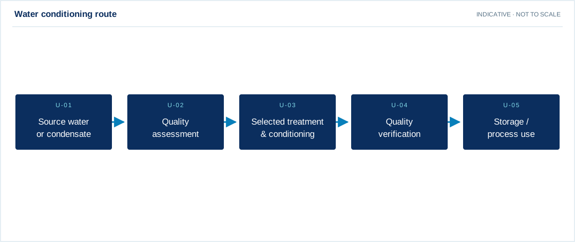
PROCESS FLOW DIAGRAM
Water conditioning route
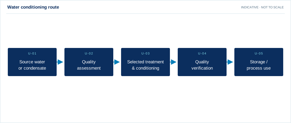
Swipe the diagram to view every stage.
- The treatment combination is established from source-water analysis and the final use specification.
Indicative process overview. Equipment tags identify functional blocks only. Final PFDs, P&IDs, duties, sizes, valves and instruments are developed from the approved project design basis.
EQUIPMENT DRAWINGS
2D layout & exploded component views.
Review the functional arrangement and the components that make up the equipment.


EXPLODED VIEW
Understand the assembly.
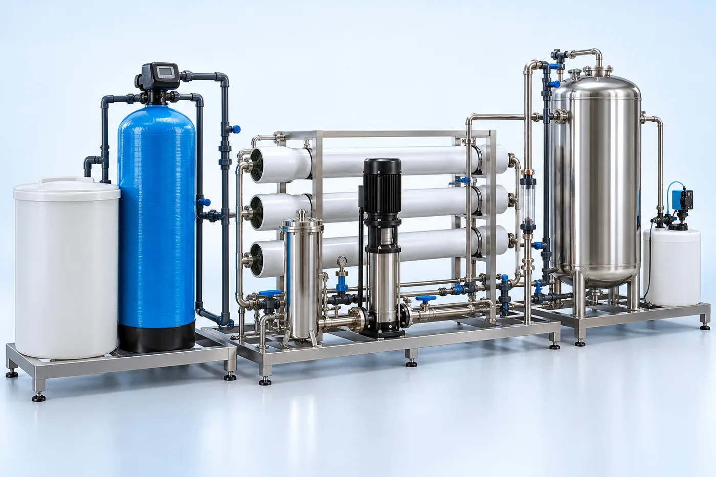
The separated component schematic identifies the main equipment groups. Vendor-specific internal geometry is established during detailed engineering.
- Feed conditioning and cartridge filtration
- High-pressure feed pump
- Membrane pressure housings
- Spiral-wound membrane elements
- Permeate and concentrate manifolds
- Pressure, conductivity and flow instruments
- Cleaning connections and control panel