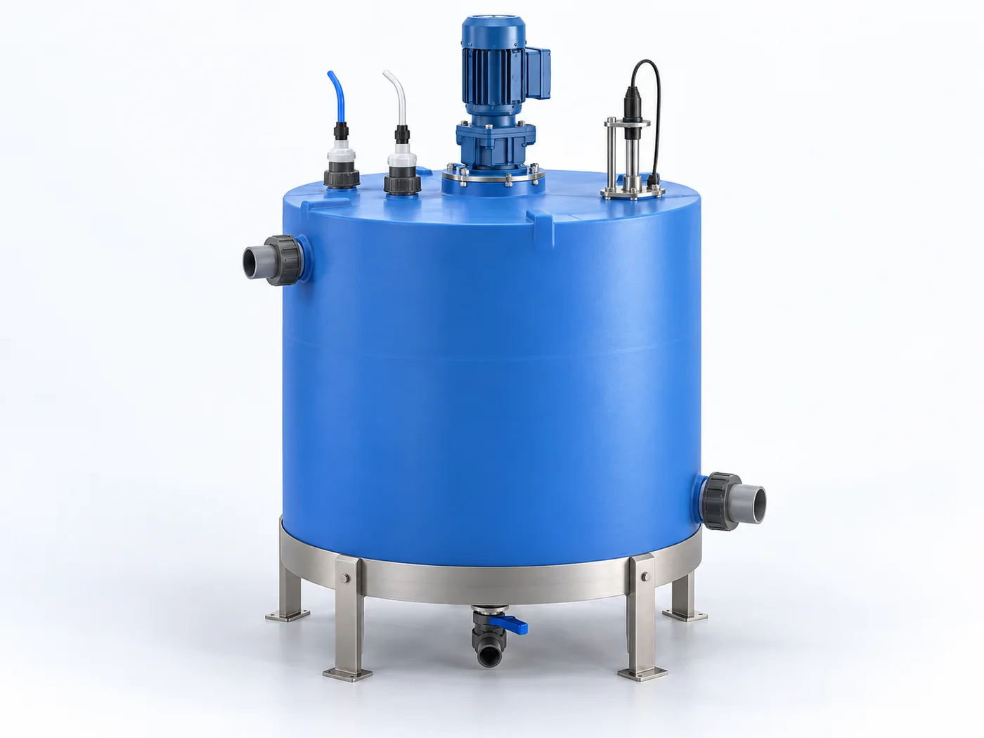
PRODUCT DESCRIPTION & TECHNICAL DOCUMENTS
How neutralization tank fits your process.
Operating principle
pH adjustment equipment configured around wastewater chemistry and titration data.
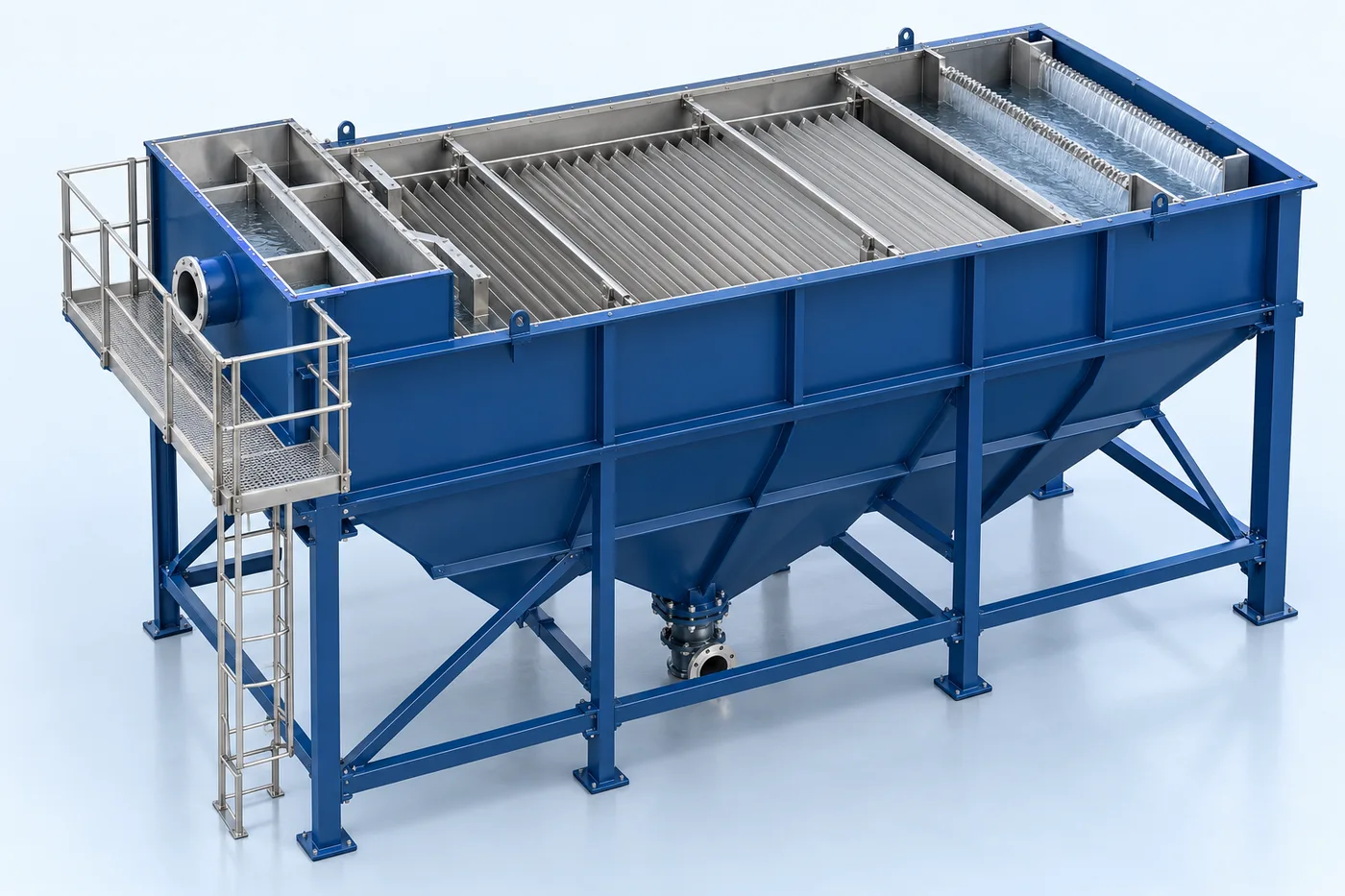
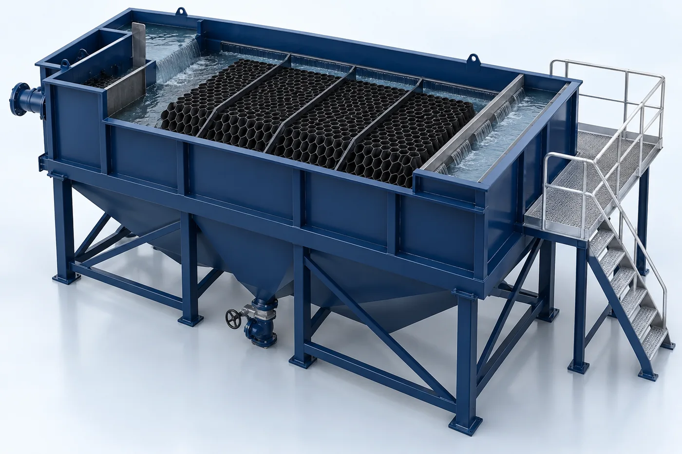
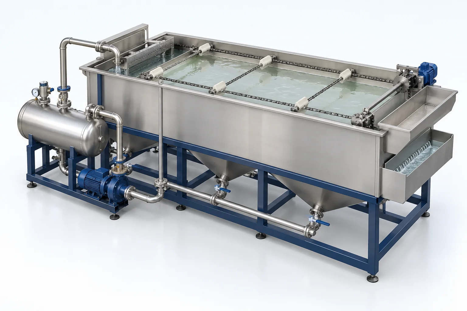
A process vessel provides the required storage, contact or reaction volume. Geometry, pressure or vacuum, fluid compatibility and site loads govern the mechanical design.
Engineering checks
- Working and gross volume with freeboard
- Design pressure, vacuum and temperature
- Corrosion, loads and design-code basis
- Nozzle schedule, access and lifting arrangement
Configuration & equipment
- Shell / tank body
- Top closure or roof as selected
- Bottom / head arrangement
- Process nozzles and manway
- Supports and foundations interface
- Internals and accessories as required
Configuration options are reviewed against the project duty. Supply quantities and final scope are defined in the approved proposal.
| Process / operating item | Engineering requirement |
|---|---|
| Process review 1 | Mixing, pH control or chemical addition is included only where required by the selected process duty. |
| Operating and maintenance | Inspect corrosion and coating condition. Check nozzles, supports and seals. Use an approved isolation and entry procedure. |
| Documentation | Project-specific datasheet, PFD, P&ID, equipment GA, electrical load list and O&M documentation as agreed. |
PDF & DRAWING DOWNLOADS
Keep the technical references.
Read the wastewater treatment brochure, or download the process and arrangement drawings below.
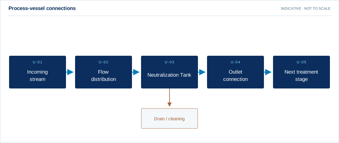
PROCESS FLOW DIAGRAM
Process-vessel connections
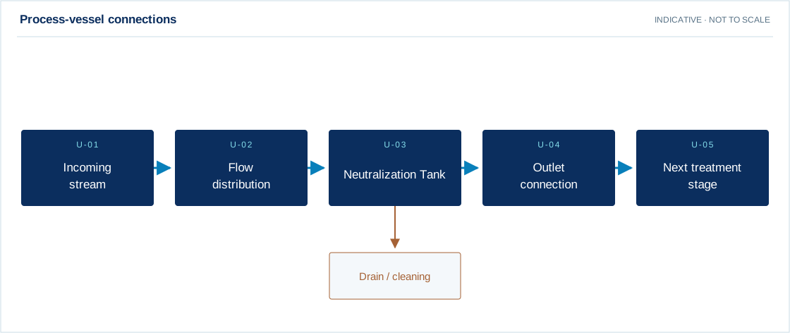
Swipe the diagram to view every stage.
- Mixing, pH control or chemical addition is included only where required by the selected process duty.
Indicative process overview. Equipment tags identify functional blocks only. Final PFDs, P&IDs, duties, sizes, valves and instruments are developed from the approved project design basis.
EQUIPMENT DRAWINGS
2D layout & exploded component views.
Review the functional arrangement and the components that make up the equipment.


EXPLODED VIEW
Understand the assembly.
The separated component schematic identifies the main equipment groups. Vendor-specific internal geometry is established during detailed engineering.
- Shell / tank body
- Top closure or roof as selected
- Bottom / head arrangement
- Process nozzles and manway
- Supports and foundations interface
- Internals and accessories as required