PRODUCT DESCRIPTION & TECHNICAL DOCUMENTS
How lamella clarifier fits your process.
Operating principle
Inclined-plate clarification selected around settleability and projected surface loading.
Gravity separation removes settleable solids. Surface loading, solids characteristics and sludge removal determine the separation arrangement and effective settling area.
Engineering checks
- Flow range and projected settling area
- Settling tests and solids loading
- Weir loading and hydraulic distribution
- Sludge removal and access
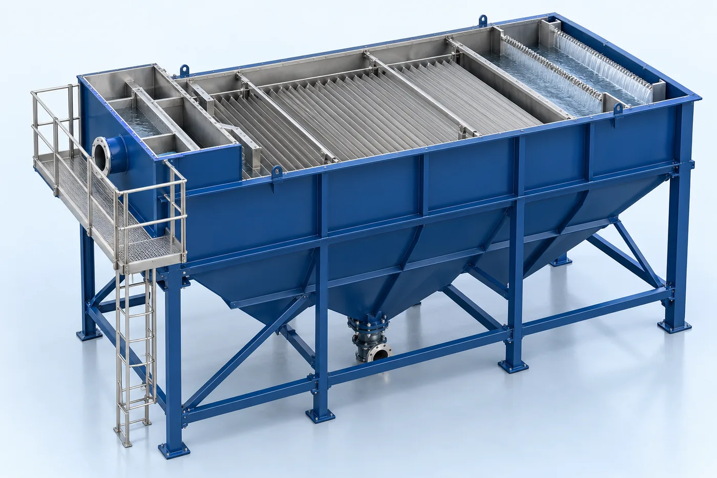
Configuration & equipment
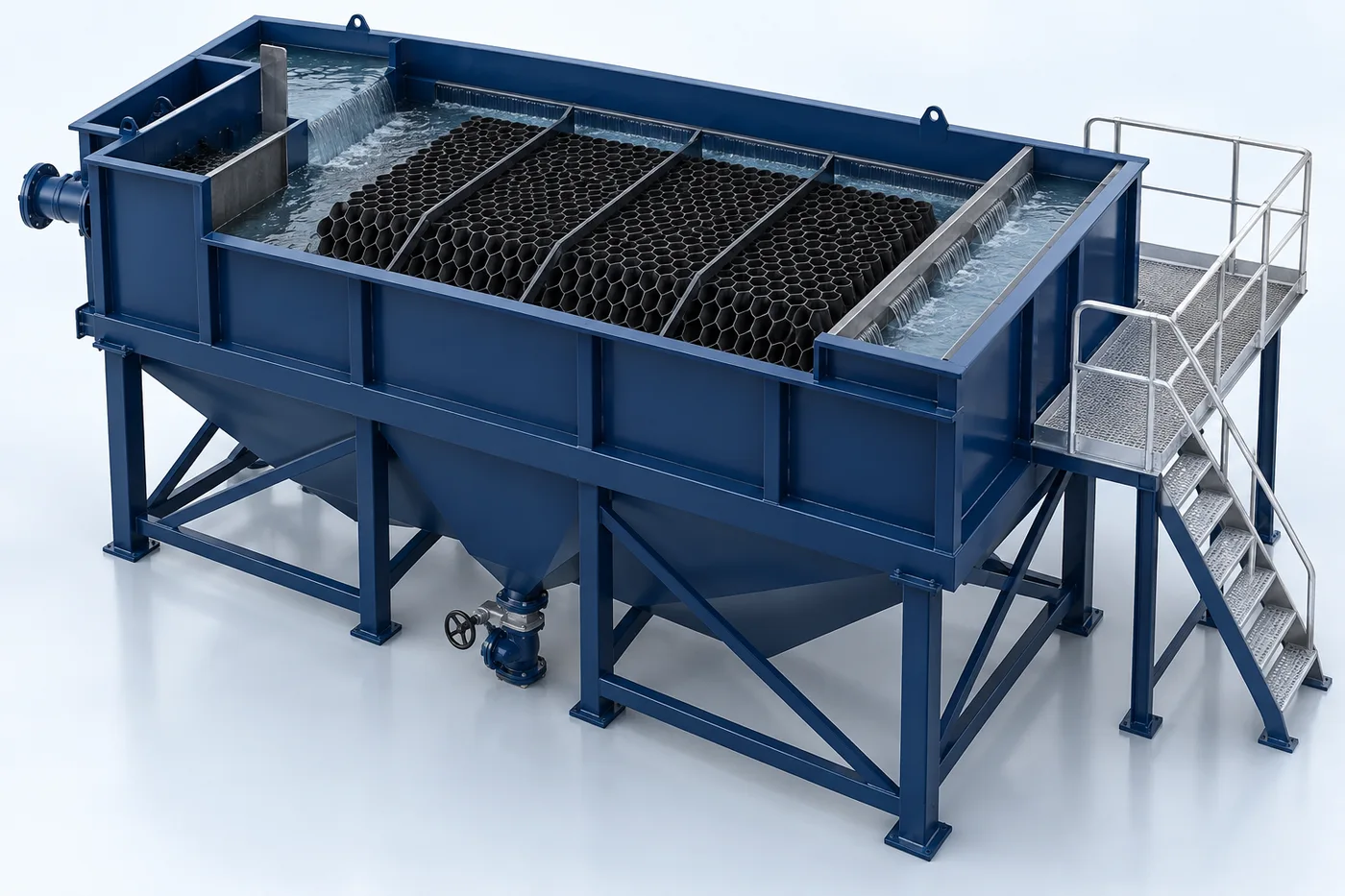
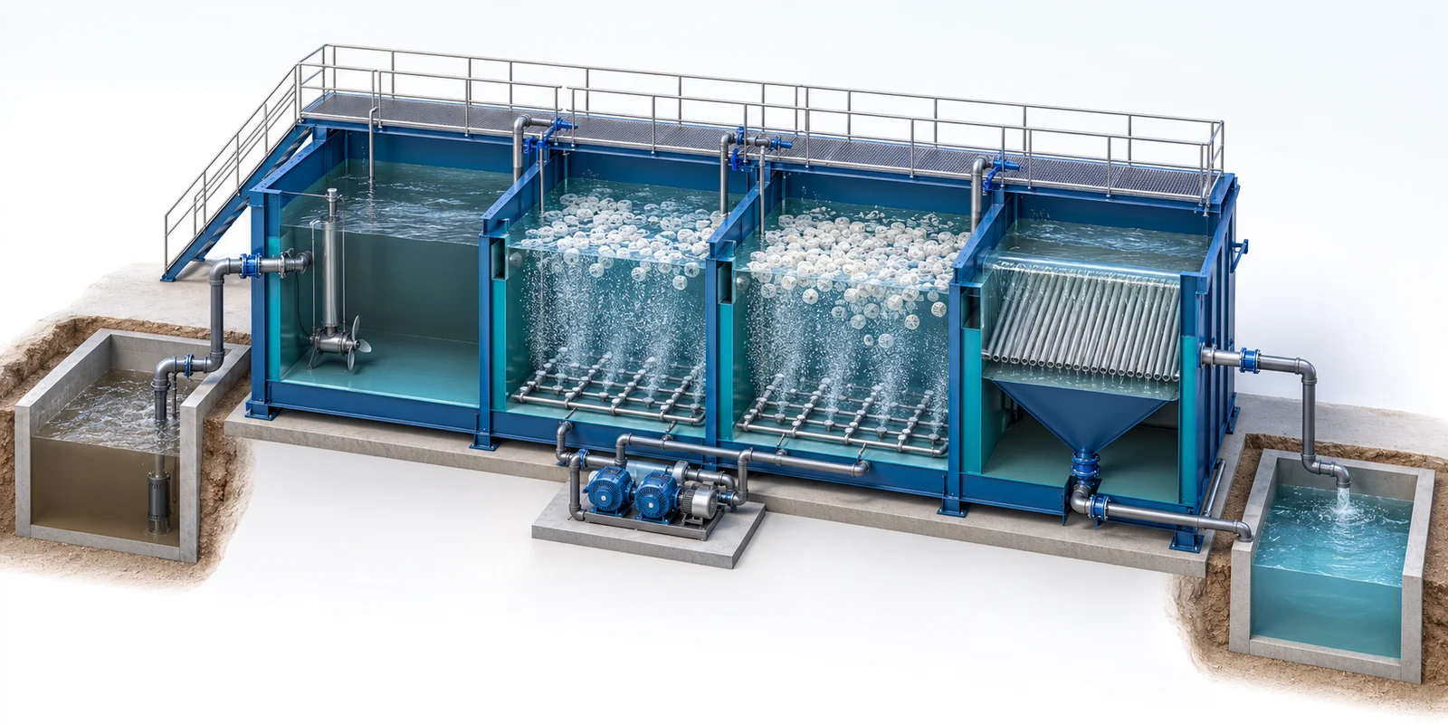
- Inlet distribution zone
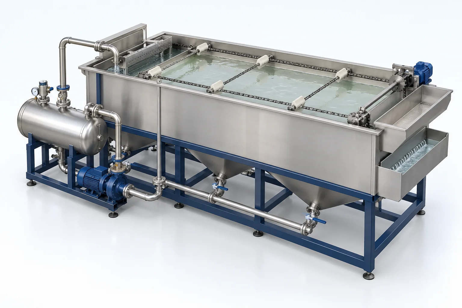
- Settling compartment
- Tube / plate modules where selected
- Clarified-water collection
- Sludge hopper or withdrawal zone
- Drain and access provisions
Configuration options are reviewed against the project duty. Supply quantities and final scope are defined in the approved proposal.
| Process / operating item | Engineering requirement |
|---|---|
| Process review 1 | Lamella plates, tube media or conventional settling are selected for the solids duty. |
| Operating and maintenance | Check uniform distribution and water level. Remove accumulated sludge routinely. Inspect modules and collection weirs. |
| Documentation | Project-specific datasheet, PFD, P&ID, equipment GA, electrical load list and O&M documentation as agreed. |
PDF & DRAWING DOWNLOADS
Keep the technical references.
Read the wastewater treatment brochure, or download the process and arrangement drawings below.
PROCESS FLOW DIAGRAM
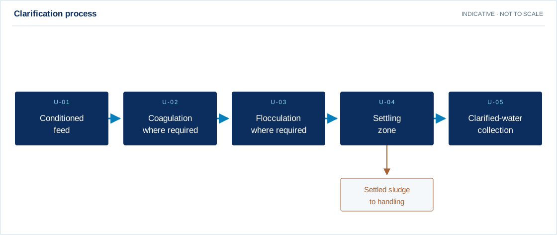
Clarification process
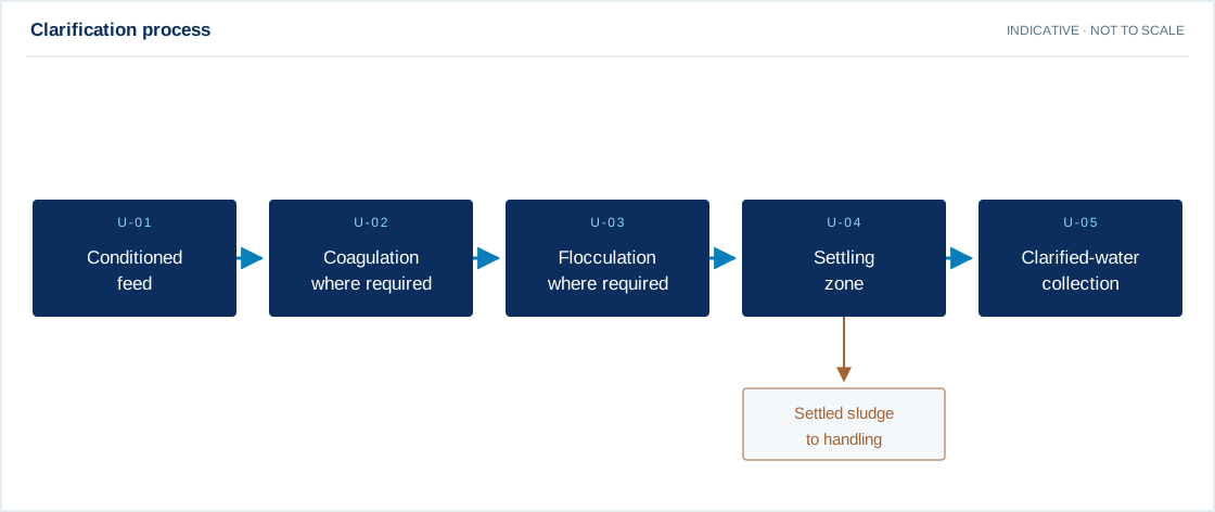
Swipe the diagram to view every stage.
- Lamella plates, tube media or conventional settling are selected for the solids duty.
Indicative process overview. Equipment tags identify functional blocks only. Final PFDs, P&IDs, duties, sizes, valves and instruments are developed from the approved project design basis.
EQUIPMENT DRAWINGS
2D layout & exploded component views.
Review the functional arrangement and the components that make up the equipment.


EXPLODED VIEW
Understand the assembly.
The separated component schematic identifies the main equipment groups. Vendor-specific internal geometry is established during detailed engineering.
- Inlet distribution zone
- Settling compartment
- Tube / plate modules where selected
- Clarified-water collection
- Sludge hopper or withdrawal zone
- Drain and access provisions