
PRODUCT DESCRIPTION & TECHNICAL DOCUMENTS
How integrated zld plant fits your process.
Operating principle
Integrated effluent treatment, membrane recovery and thermal concentration for ZLD objectives.
An integrated recovery train combines pretreatment, membrane separation and thermal concentration. Every concentrate, cleaning waste and residual stream needs an explicit management route.
Engineering checks
- Complete water and dissolved-solids balance
- Scaling and fouling at each recovery stage
- Utility and condensate-quality requirements
- Residual-water and solid-waste management
Configuration & equipment
- Effluent pretreatment interface
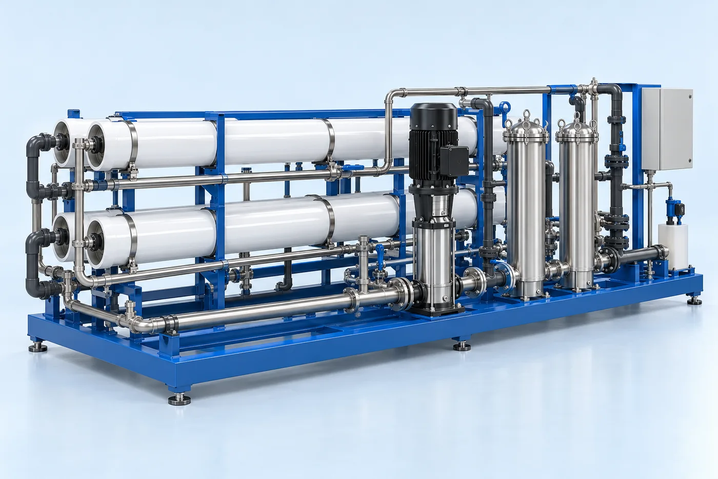
- Membrane recovery stages
- Concentrate collection and conditioning
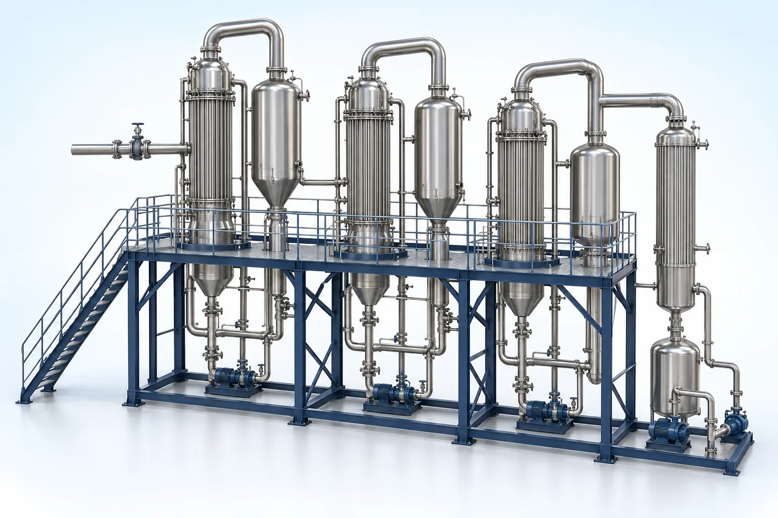
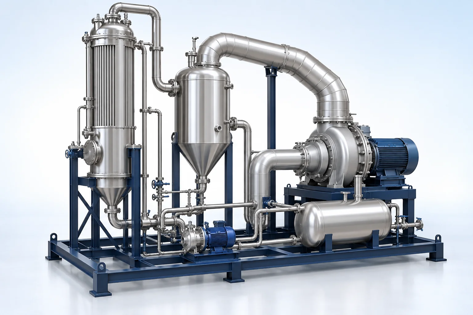
- Thermal concentration / drying route
- Condensate and permeate recovery
- Solid-residue handling
- Plant monitoring and control
Configuration options are reviewed against the project duty. Supply quantities and final scope are defined in the approved proposal.
| Process / operating item | Engineering requirement |
|---|---|
| Process review 1 | The main line after RO follows the concentrate stream. |
| Process review 2 | Recovered water quality, all residual liquids, cleaning streams and solids disposal must be included in the final balance. |
| Operating and maintenance | Trend stagewise mass balance and quality. Coordinate cleaning of membrane and thermal sections. Track residue generation and disposal. |
| Documentation | Project-specific datasheet, PFD, P&ID, equipment GA, electrical load list and O&M documentation as agreed. |
PDF & DRAWING DOWNLOADS
Keep the technical references.
Read the zld & recovery brochure, or download the process and arrangement drawings below.
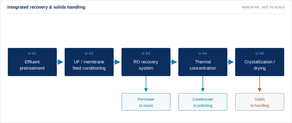
PROCESS FLOW DIAGRAM
Integrated recovery & solids handling
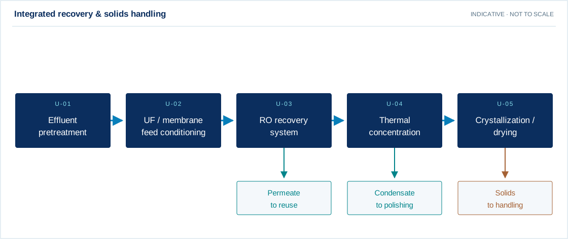
Swipe the diagram to view every stage.
- The main line after RO follows the concentrate stream.
- Recovered water quality, all residual liquids, cleaning streams and solids disposal must be included in the final balance.
Indicative process overview. Equipment tags identify functional blocks only. Final PFDs, P&IDs, duties, sizes, valves and instruments are developed from the approved project design basis.
EQUIPMENT DRAWINGS
2D layout & exploded component views.
Review the functional arrangement and the components that make up the equipment.


EXPLODED VIEW
Understand the assembly.
The separated component schematic identifies the main equipment groups. Vendor-specific internal geometry is established during detailed engineering.
- Effluent pretreatment interface
- Membrane recovery stages
- Concentrate collection and conditioning
- Thermal concentration / drying route
- Condensate and permeate recovery
- Solid-residue handling
- Plant monitoring and control