PRODUCT DESCRIPTION & TECHNICAL DOCUMENTS
How industrial process piping fits your process.
Operating principle
Industrial piping packages configured around fluid service, hydraulics and mechanical requirements.
Piping transfers fluids between equipment. Hydraulic sizing, pressure class, material compatibility, thermal movement and maintainability must be coordinated.
Engineering checks
- Actual bore, velocity and pressure loss
- Design pressure, temperature and material
- Expansion, stress and support loads
- Drainability, vents and maintenance access
Configuration & equipment
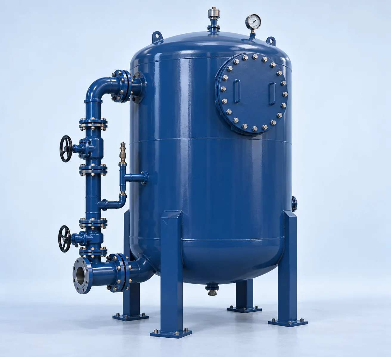
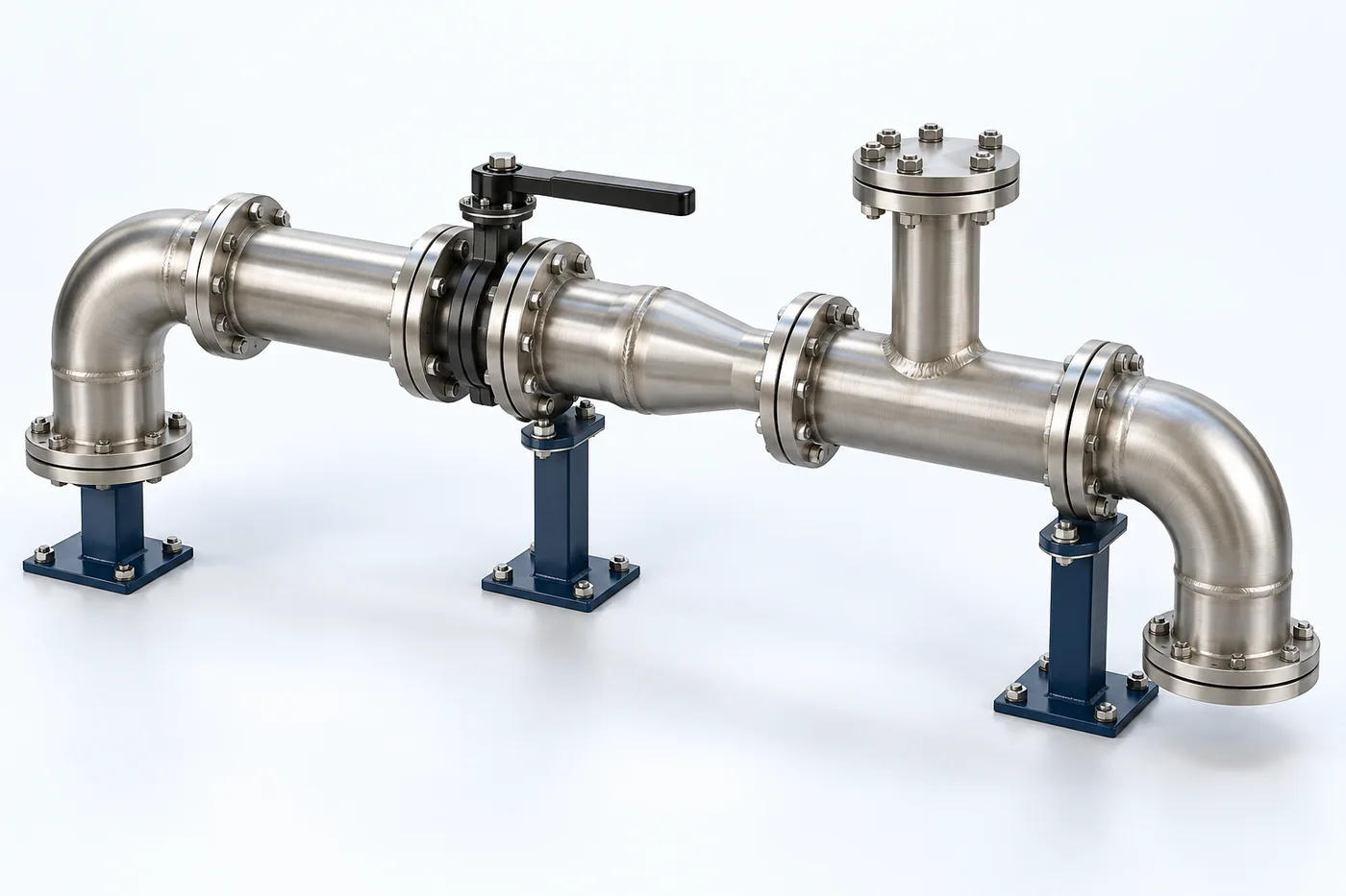
- Pipe spools
- Bends, reducers and branches
- Isolation and control valves
- Flanged / welded connections
- Gaskets and fasteners
- Supports, guides and anchors
Configuration options are reviewed against the project duty. Supply quantities and final scope are defined in the approved proposal.
| Process / operating item | Engineering requirement |
|---|---|
| Process review 1 | Pipe size, supports, expansion, pressure class and materials require mechanical and hydraulic design. |
| Operating and maintenance | Inspect leaks and corrosion. Check supports and movement. Service valves and joints with safe isolation. |
| Documentation | Project-specific datasheet, PFD, P&ID, equipment GA, electrical load list and O&M documentation as agreed. |
PDF & DRAWING DOWNLOADS
Keep the technical references.
Read the process equipment brochure, or download the process and arrangement drawings below.
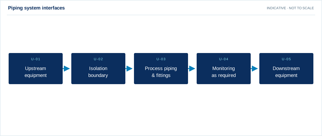
PROCESS FLOW DIAGRAM
Piping system interfaces
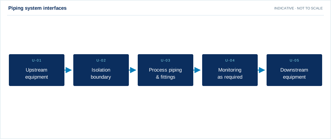
Swipe the diagram to view every stage.
- Pipe size, supports, expansion, pressure class and materials require mechanical and hydraulic design.
Indicative process overview. Equipment tags identify functional blocks only. Final PFDs, P&IDs, duties, sizes, valves and instruments are developed from the approved project design basis.
EQUIPMENT DRAWINGS
2D layout & exploded component views.
Review the functional arrangement and the components that make up the equipment.


EXPLODED VIEW
Understand the assembly.
The separated component schematic identifies the main equipment groups. Vendor-specific internal geometry is established during detailed engineering.
- Pipe spools
- Bends, reducers and branches
- Isolation and control valves
- Flanged / welded connections
- Gaskets and fasteners
- Supports, guides and anchors