PRODUCT DESCRIPTION & TECHNICAL DOCUMENTS
How electroplating / metal finishing etp fits your process.
Operating principle
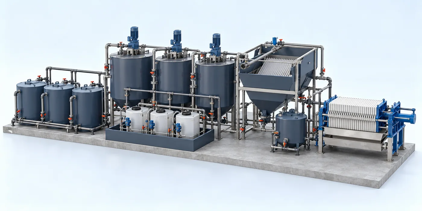
Treatment configured around metal-bearing streams, speciation and chemical compatibility.
Physical and chemical treatment is selected from segregated effluent analysis and treatability tests. Depending on the contaminants, the train may include controlled chemical reaction, coagulation, flocculation, solids separation and polishing.
Engineering checks
- Stream-specific chemistry and incompatible constituents
- Laboratory / jar-test basis for reaction and dose
- Hydraulic loading and solid-liquid separation tests
- Sludge characterization and downstream polishing
Configuration & equipment
- Stream segregation and equalization
- Controlled reaction / neutralization stages
- Chemical preparation and metering
- Rapid mixing and flocculation where required
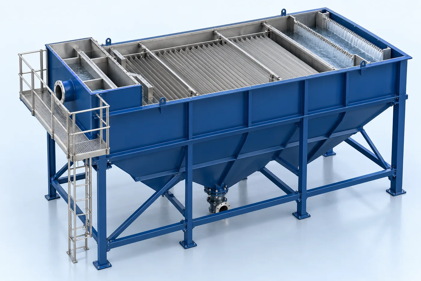
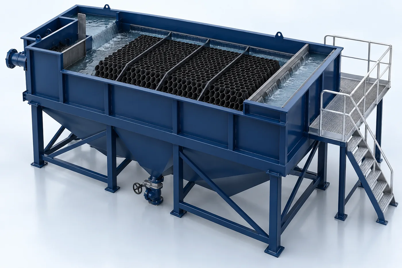
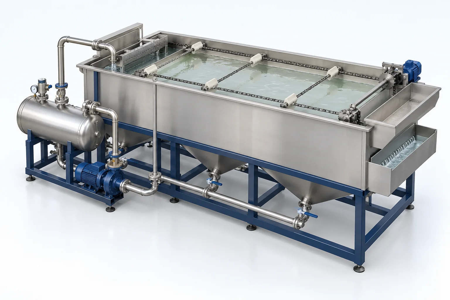
- Settling or flotation selected by testing
- Sludge collection and dewatering
- Sampling and process controls
Configuration options are reviewed against the project duty. Supply quantities and final scope are defined in the approved proposal.
| Process / operating item | Engineering requirement |
|---|---|
| Process review 1 | Cyanide- and chromium-bearing streams may require separate, specific pretreatment. |
| Process review 2 | Chemistry, sludge classification and residual handling require project-specific review. |
| Operating and maintenance | Inspect alignment and vibration. Check lubrication and fasteners. Inspect shaft, impeller and supports. |
| Documentation | Project-specific datasheet, PFD, P&ID, equipment GA, electrical load list and O&M documentation as agreed. |
PDF & DRAWING DOWNLOADS
Keep the technical references.
Read the wastewater treatment brochure, or download the process and arrangement drawings below.
PROCESS FLOW DIAGRAM
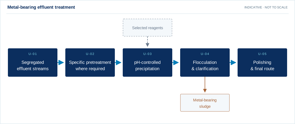
Metal-bearing effluent treatment
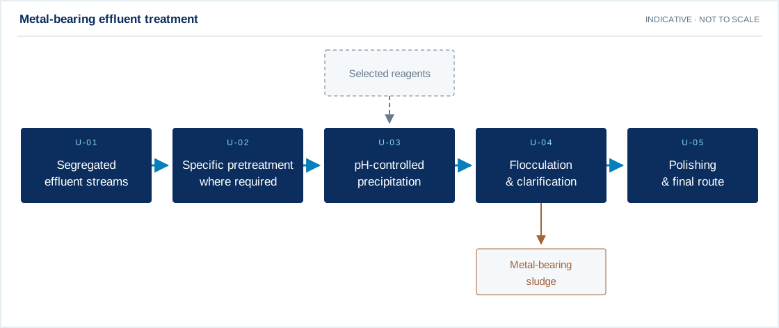
Swipe the diagram to view every stage.
- Cyanide- and chromium-bearing streams may require separate, specific pretreatment.
- Chemistry, sludge classification and residual handling require project-specific review.
Indicative process overview. Equipment tags identify functional blocks only. Final PFDs, P&IDs, duties, sizes, valves and instruments are developed from the approved project design basis.
EQUIPMENT DRAWINGS
2D layout & exploded component views.
Review the functional arrangement and the components that make up the equipment.


EXPLODED VIEW
Understand the assembly.
The separated component schematic identifies the main equipment groups. Vendor-specific internal geometry is established during detailed engineering.
- Stream segregation and equalization
- Controlled reaction / neutralization stages
- Chemical preparation and metering
- Rapid mixing and flocculation where required
- Settling or flotation selected by testing
- Sludge collection and dewatering
- Sampling and process controls