
Water treatment
Demineralization (DM) Plant
Ion-exchange treatment for reducing dissolved ionic content in water.
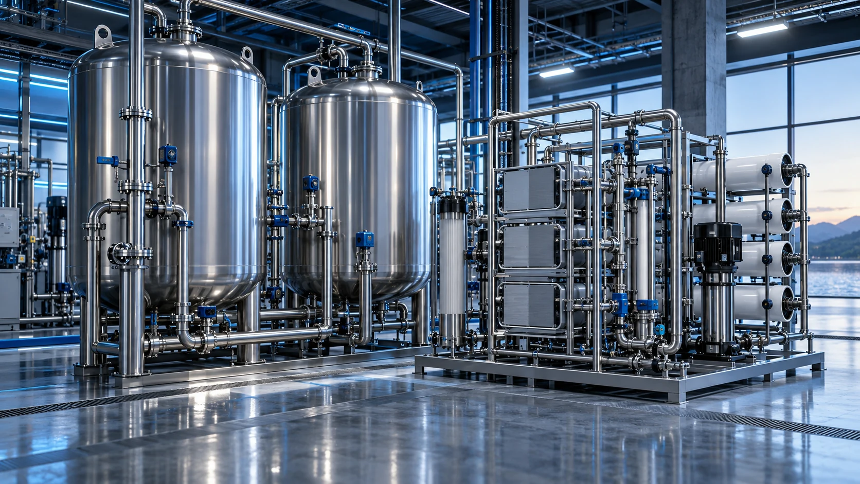
SYSTEM VIEW
See the equipment.
Understand the process.
The render illustrates the DM & EDI systems equipment family. Your final arrangement follows the project duty, site layout and approved design.
View process flow Browse the visual galleryConceptual 3D visualization · equipment details are illustrative.
PROCESS FLOW DIAGRAM
Ion-exchange demineralization
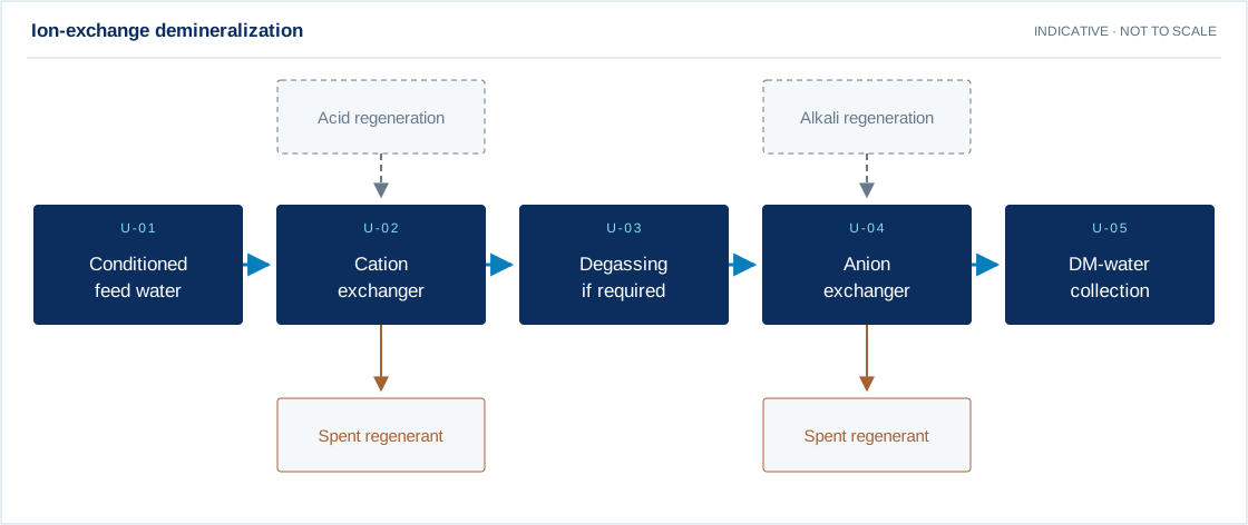
Swipe the diagram to view every stage.
- Degassing and polishing are selected for the feed chemistry and product-water quality.
- Acid and alkali regeneration effluents require neutralization and controlled handling.
Indicative process overview. Equipment tags identify functional blocks only. Final PFDs, P&IDs, duties, sizes, valves and instruments are developed from the approved project design basis.
PROCESS & EQUIPMENT DETAILS
How demineralization (dm) plant fits your process.
Operating principle
Ion-exchange treatment for reducing dissolved ionic content in water.
Water passes through a selected media or resin bed. Separation, adsorption or ion exchange depends on the media duty; backwash or regeneration restores the relevant operating condition.
Engineering checks
- Service flow and selected hydraulic loading
- Bed depth, contact time and freeboard
- Backwash expansion or regeneration demand
- Design pressure, materials and corrosion compatibility
Configuration & equipment
- Vessel shell and access closure
- Inlet distributor
- Selected media or resin bed
- Supporting layer where specified
- Underdrain / collection system
- Service and backwash valve manifold
- Drain and sampling connections
Configuration options are reviewed against the project duty. Supply quantities and final scope are defined in the approved proposal.
| Process / operating item | Engineering requirement |
|---|---|
| Process review 1 | Degassing and polishing are selected for the feed chemistry and product-water quality. |
| Process review 2 | Acid and alkali regeneration effluents require neutralization and controlled handling. |
| Operating and maintenance | Record inlet/outlet pressure and water quality. Inspect media loss and distribution. Carry out backwash or regeneration to approved procedures. |
| Documentation | Project-specific datasheet, PFD, P&ID, equipment GA, electrical load list and O&M documentation as agreed. |
EQUIPMENT DRAWINGS
2D layout & exploded component views.
Review the functional arrangement and the components that make up the equipment.
%20Plant%20%E2%80%94%202D%20functional%20arrangement%3C%2Ftitle%3E%3Cdesc%3EIllustrative%20equipment%20arrangement%20without%20project%20dimensions%20or%20construction%20specifications.%3C%2Fdesc%3E%3Cdefs%3E%3Cmarker%20id%3D%22arrow%22%20viewBox%3D%220%200%2010%2010%22%20refX%3D%229%22%20refY%3D%225%22%20markerWidth%3D%226%22%20markerHeight%3D%226%22%20orient%3D%22auto-start-reverse%22%3E%3Cpath%20d%3D%22M0%200L10%205L0%2010Z%22%20fill%3D%22%23008ab0%22%2F%3E%3C%2Fmarker%3E%3Cpattern%20id%3D%22grid%22%20width%3D%2220%22%20height%3D%2220%22%20patternUnits%3D%22userSpaceOnUse%22%3E%3Cpath%20d%3D%22M20%200H0V20%22%20fill%3D%22none%22%20stroke%3D%22%23e6f0f5%22%20stroke-width%3D%22.5%22%2F%3E%3C%2Fpattern%3E%3C%2Fdefs%3E%3Crect%20width%3D%221120%22%20height%3D%22780%22%20fill%3D%22white%22%2F%3E%3Crect%20x%3D%2220%22%20y%3D%2220%22%20width%3D%221080%22%20height%3D%22740%22%20fill%3D%22url(%23grid)%22%20stroke%3D%22%230b2e5e%22%20stroke-width%3D%222%22%2F%3E%3Cg%20font-family%3D%22Arial%2CHelvetica%2Csans-serif%22%3E%3Ctext%20x%3D%2246%22%20y%3D%2256%22%20font-size%3D%2217%22%20text-anchor%3D%22start%22%20fill%3D%22%230b2e5e%22%3ERAIN%20POWER%20FILTRATION%3C%2Ftext%3E%3Ctext%20x%3D%221075%22%20y%3D%2256%22%20font-size%3D%2213%22%20text-anchor%3D%22end%22%20fill%3D%22%230b2e5e%22%3EENGINEERING%20REFERENCE%20%C2%B7%20NOT%20TO%20SCALE%3C%2Ftext%3E%3Cpath%20d%3D%22M20%2077H1100%22%20stroke%3D%22%230b2e5e%22%2F%3E%3Ctext%20x%3D%2246%22%20y%3D%22112%22%20font-size%3D%2225%22%20text-anchor%3D%22start%22%20fill%3D%22%230b2e5e%22%3EDemineralization%20(DM)%20Plant%3C%2Ftext%3E%3Ctext%20x%3D%2246%22%20y%3D%22141%22%20font-size%3D%2216%22%20text-anchor%3D%22start%22%20fill%3D%22%230b2e5e%22%3E2D%20functional%20equipment%20arrangement%3C%2Ftext%3E%3Cg%20stroke%3D%22%230b2e5e%22%20stroke-width%3D%222%22%20fill%3D%22none%22%3E%3Cpath%20d%3D%22M104%2C213%20Q160%2C191%20216%2C213%20V259%20Q160%2C281%20104%2C259Z%20M104%2C213%20Q160%2C235%20216%2C213%22%2F%3E%3C%2Fg%3E%3Ccircle%20cx%3D%2277%22%20cy%3D%22218%22%20r%3D%2215%22%20fill%3D%22%230b2e5e%22%2F%3E%3Ctext%20x%3D%2277%22%20y%3D%22223%22%20font-size%3D%2213%22%20text-anchor%3D%22middle%22%20fill%3D%22white%22%3E01%3C%2Ftext%3E%3Ctext%20x%3D%2268%22%20y%3D%22307%22%20font-size%3D%2215%22%20text-anchor%3D%22start%22%20fill%3D%22%230b2e5e%22%3EVessel%20shell%20and%20access%3C%2Ftext%3E%3Ctext%20x%3D%2268%22%20y%3D%22327%22%20font-size%3D%2215%22%20text-anchor%3D%22start%22%20fill%3D%22%230b2e5e%22%3Eclosure%3C%2Ftext%3E%3Cpath%20d%3D%22M218%2C236%20H302%22%20stroke%3D%22%23008ab0%22%20stroke-width%3D%222%22%20marker-end%3D%22url(%23arrow)%22%2F%3E%3Cg%20stroke%3D%22%230b2e5e%22%20stroke-width%3D%222%22%20fill%3D%22none%22%3E%3Crect%20x%3D%22370%22%20y%3D%22200%22%20width%3D%22112%22%20height%3D%2272%22%2F%3E%3Cpath%20d%3D%22M380%2C262%20H472%22%2F%3E%3C%2Fg%3E%3Ccircle%20cx%3D%22343%22%20cy%3D%22218%22%20r%3D%2215%22%20fill%3D%22%230b2e5e%22%2F%3E%3Ctext%20x%3D%22343%22%20y%3D%22223%22%20font-size%3D%2213%22%20text-anchor%3D%22middle%22%20fill%3D%22white%22%3E02%3C%2Ftext%3E%3Ctext%20x%3D%22334%22%20y%3D%22307%22%20font-size%3D%2215%22%20text-anchor%3D%22start%22%20fill%3D%22%230b2e5e%22%3EInlet%20distributor%3C%2Ftext%3E%3Cpath%20d%3D%22M484%2C236%20H568%22%20stroke%3D%22%23008ab0%22%20stroke-width%3D%222%22%20marker-end%3D%22url(%23arrow)%22%2F%3E%3Cg%20stroke%3D%22%230b2e5e%22%20stroke-width%3D%222%22%20fill%3D%22none%22%3E%3Crect%20x%3D%22636%22%20y%3D%22200%22%20width%3D%22112%22%20height%3D%2272%22%2F%3E%3Cpath%20d%3D%22M658.4%2C200%20V272%22%2F%3E%3Cpath%20d%3D%22M680.8%2C200%20V272%22%2F%3E%3Cpath%20d%3D%22M703.2%2C200%20V272%22%2F%3E%3Cpath%20d%3D%22M725.6%2C200%20V272%22%2F%3E%3C%2Fg%3E%3Ccircle%20cx%3D%22609%22%20cy%3D%22218%22%20r%3D%2215%22%20fill%3D%22%230b2e5e%22%2F%3E%3Ctext%20x%3D%22609%22%20y%3D%22223%22%20font-size%3D%2213%22%20text-anchor%3D%22middle%22%20fill%3D%22white%22%3E03%3C%2Ftext%3E%3Ctext%20x%3D%22600%22%20y%3D%22307%22%20font-size%3D%2215%22%20text-anchor%3D%22start%22%20fill%3D%22%230b2e5e%22%3ESelected%20media%20or%20resin%20bed%3C%2Ftext%3E%3Cpath%20d%3D%22M750%2C236%20H834%22%20stroke%3D%22%23008ab0%22%20stroke-width%3D%222%22%20marker-end%3D%22url(%23arrow)%22%2F%3E%3Cg%20stroke%3D%22%230b2e5e%22%20stroke-width%3D%222%22%20fill%3D%22none%22%3E%3Crect%20x%3D%22902%22%20y%3D%22200%22%20width%3D%22112%22%20height%3D%2272%22%2F%3E%3Cpath%20d%3D%22M912%2C262%20H1004%22%2F%3E%3C%2Fg%3E%3Ccircle%20cx%3D%22875%22%20cy%3D%22218%22%20r%3D%2215%22%20fill%3D%22%230b2e5e%22%2F%3E%3Ctext%20x%3D%22875%22%20y%3D%22223%22%20font-size%3D%2213%22%20text-anchor%3D%22middle%22%20fill%3D%22white%22%3E04%3C%2Ftext%3E%3Ctext%20x%3D%22866%22%20y%3D%22307%22%20font-size%3D%2215%22%20text-anchor%3D%22start%22%20fill%3D%22%230b2e5e%22%3ESupporting%20layer%20where%3C%2Ftext%3E%3Ctext%20x%3D%22866%22%20y%3D%22327%22%20font-size%3D%2215%22%20text-anchor%3D%22start%22%20fill%3D%22%230b2e5e%22%3Especified%3C%2Ftext%3E%3Cg%20stroke%3D%22%230b2e5e%22%20stroke-width%3D%222%22%20fill%3D%22none%22%3E%3Crect%20x%3D%22104%22%20y%3D%22402%22%20width%3D%22112%22%20height%3D%2272%22%2F%3E%3Cpath%20d%3D%22M114%2C464%20H206%22%2F%3E%3C%2Fg%3E%3Ccircle%20cx%3D%2277%22%20cy%3D%22420%22%20r%3D%2215%22%20fill%3D%22%230b2e5e%22%2F%3E%3Ctext%20x%3D%2277%22%20y%3D%22425%22%20font-size%3D%2213%22%20text-anchor%3D%22middle%22%20fill%3D%22white%22%3E05%3C%2Ftext%3E%3Ctext%20x%3D%2268%22%20y%3D%22509%22%20font-size%3D%2215%22%20text-anchor%3D%22start%22%20fill%3D%22%230b2e5e%22%3EUnderdrain%20%2F%20collection%3C%2Ftext%3E%3Ctext%20x%3D%2268%22%20y%3D%22529%22%20font-size%3D%2215%22%20text-anchor%3D%22start%22%20fill%3D%22%230b2e5e%22%3Esystem%3C%2Ftext%3E%3Cpath%20d%3D%22M218%2C438%20H302%22%20stroke%3D%22%23008ab0%22%20stroke-width%3D%222%22%20marker-end%3D%22url(%23arrow)%22%2F%3E%3Cg%20stroke%3D%22%230b2e5e%22%20stroke-width%3D%222%22%20fill%3D%22none%22%3E%3Cpath%20d%3D%22M370%2C412%20L482%2C464%20V412%20L370%2C464Z%20M426%2C438%20V394%20M409%2C394%20H443%22%2F%3E%3C%2Fg%3E%3Ccircle%20cx%3D%22343%22%20cy%3D%22420%22%20r%3D%2215%22%20fill%3D%22%230b2e5e%22%2F%3E%3Ctext%20x%3D%22343%22%20y%3D%22425%22%20font-size%3D%2213%22%20text-anchor%3D%22middle%22%20fill%3D%22white%22%3E06%3C%2Ftext%3E%3Ctext%20x%3D%22334%22%20y%3D%22509%22%20font-size%3D%2215%22%20text-anchor%3D%22start%22%20fill%3D%22%230b2e5e%22%3EService%20and%20backwash%20valve%3C%2Ftext%3E%3Ctext%20x%3D%22334%22%20y%3D%22529%22%20font-size%3D%2215%22%20text-anchor%3D%22start%22%20fill%3D%22%230b2e5e%22%3Emanifold%3C%2Ftext%3E%3Cpath%20d%3D%22M484%2C438%20H568%22%20stroke%3D%22%23008ab0%22%20stroke-width%3D%222%22%20marker-end%3D%22url(%23arrow)%22%2F%3E%3Cg%20stroke%3D%22%230b2e5e%22%20stroke-width%3D%222%22%20fill%3D%22none%22%3E%3Crect%20x%3D%22636%22%20y%3D%22402%22%20width%3D%22112%22%20height%3D%2272%22%2F%3E%3Cpath%20d%3D%22M646%2C464%20H738%22%2F%3E%3C%2Fg%3E%3Ccircle%20cx%3D%22609%22%20cy%3D%22420%22%20r%3D%2215%22%20fill%3D%22%230b2e5e%22%2F%3E%3Ctext%20x%3D%22609%22%20y%3D%22425%22%20font-size%3D%2213%22%20text-anchor%3D%22middle%22%20fill%3D%22white%22%3E07%3C%2Ftext%3E%3Ctext%20x%3D%22600%22%20y%3D%22509%22%20font-size%3D%2215%22%20text-anchor%3D%22start%22%20fill%3D%22%230b2e5e%22%3EDrain%20and%20sampling%3C%2Ftext%3E%3Ctext%20x%3D%22600%22%20y%3D%22529%22%20font-size%3D%2215%22%20text-anchor%3D%22start%22%20fill%3D%22%230b2e5e%22%3Econnections%3C%2Ftext%3E%3Ctext%20x%3D%2258%22%20y%3D%22612%22%20font-size%3D%2215%22%20text-anchor%3D%22start%22%20fill%3D%22%230b2e5e%22%3ESymbols%20locate%20functional%20equipment%20groups%3B%20flow%20connections%20follow%20the%20PFD.%3C%2Ftext%3E%3Cpath%20d%3D%22M20%20635H1100%20M750%20635V760%20M930%20635V760%22%20stroke%3D%22%230b2e5e%22%2F%3E%3Ctext%20x%3D%2245%22%20y%3D%22665%22%20font-size%3D%2213%22%20text-anchor%3D%22start%22%20fill%3D%22%230b2e5e%22%3EDRAWING%20BASIS%3C%2Ftext%3E%3Ctext%20x%3D%2245%22%20y%3D%22690%22%20font-size%3D%2216%22%20text-anchor%3D%22start%22%20fill%3D%22%230b2e5e%22%3EEquipment-family%20reference.%20Final%20layout%2C%20quantities%2C%20materials%2C%3C%2Ftext%3E%3Ctext%20x%3D%2245%22%20y%3D%22712%22%20font-size%3D%2216%22%20text-anchor%3D%22start%22%20fill%3D%22%230b2e5e%22%3Edimensions%2C%20nozzles%20and%20maintenance%20clearances%20require%20approval.%3C%2Ftext%3E%3Ctext%20x%3D%2245%22%20y%3D%22741%22%20font-size%3D%2214%22%20text-anchor%3D%22start%22%20fill%3D%22%230b2e5e%22%3EUse%20the%20approved%20project%20GA%20and%20vendor%20drawings%20for%20construction.%3C%2Ftext%3E%3Ctext%20x%3D%22773%22%20y%3D%22664%22%20font-size%3D%2212%22%20text-anchor%3D%22start%22%20fill%3D%22%230b2e5e%22%3EVIEW%3C%2Ftext%3E%3Ctext%20x%3D%22773%22%20y%3D%22692%22%20font-size%3D%2217%22%20text-anchor%3D%22start%22%20fill%3D%22%230b2e5e%22%3ELAYOUT%3C%2Ftext%3E%3Ctext%20x%3D%22773%22%20y%3D%22732%22%20font-size%3D%2212%22%20text-anchor%3D%22start%22%20fill%3D%22%230b2e5e%22%3ESTATUS%3A%20REFERENCE%3C%2Ftext%3E%3Ctext%20x%3D%22952%22%20y%3D%22664%22%20font-size%3D%2212%22%20text-anchor%3D%22start%22%20fill%3D%22%230b2e5e%22%3ESCALE%3C%2Ftext%3E%3Ctext%20x%3D%22952%22%20y%3D%22692%22%20font-size%3D%2218%22%20text-anchor%3D%22start%22%20fill%3D%22%230b2e5e%22%3ENTS%3C%2Ftext%3E%3Ctext%20x%3D%22952%22%20y%3D%22732%22%20font-size%3D%2212%22%20text-anchor%3D%22start%22%20fill%3D%22%230b2e5e%22%3EUNITS%3A%20SI%3C%2Ftext%3E%3C%2Fg%3E%3C%2Fsvg%3E)
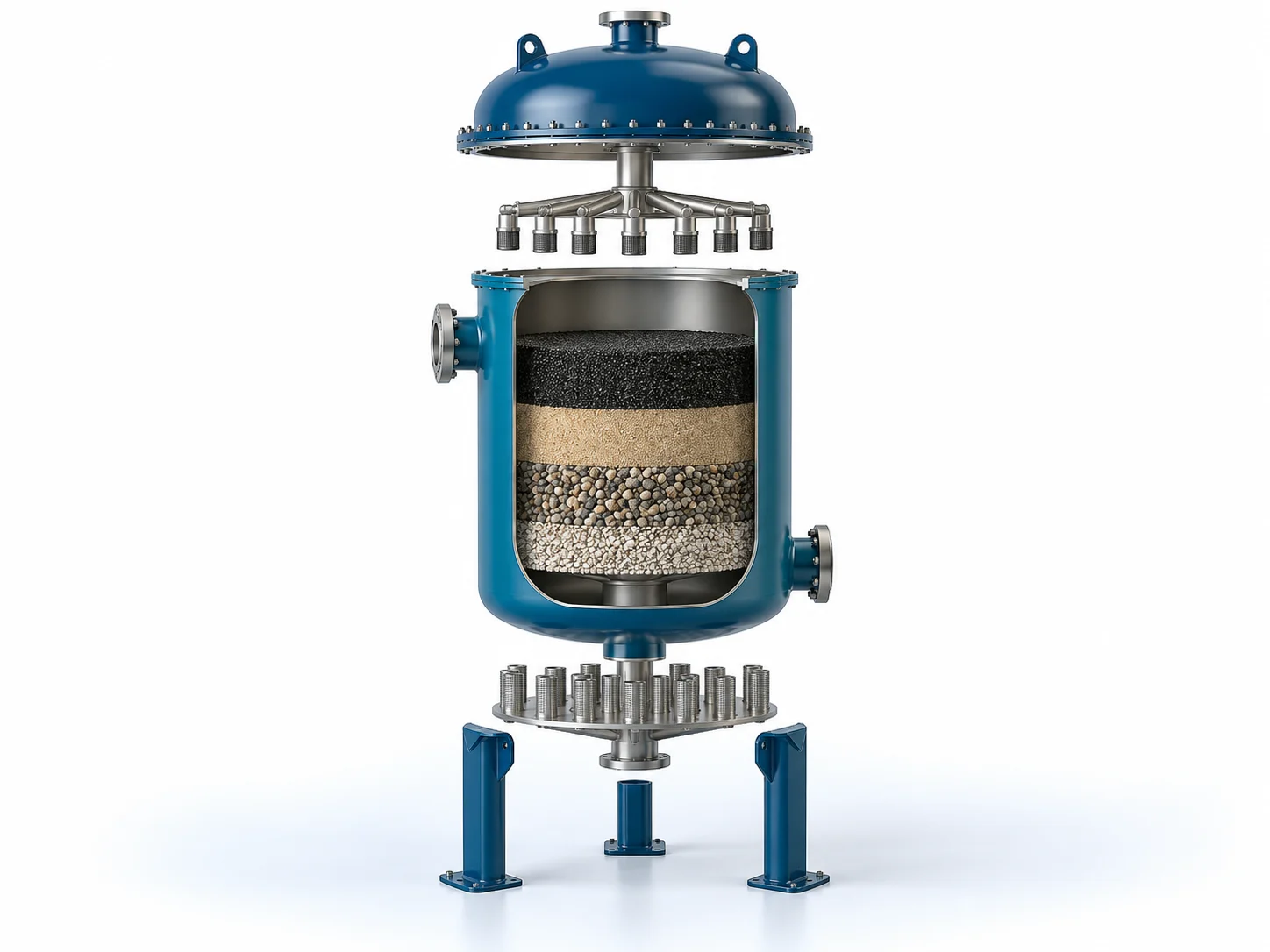
EXPLODED VIEW
Understand the assembly.
Media-filter family reference. A resin softener or ion-exchange unit uses different media and regeneration arrangements.
- Vessel shell and access closure
- Inlet distributor
- Selected media or resin bed
- Supporting layer where specified
- Underdrain / collection system
- Service and backwash valve manifold
- Drain and sampling connections
YOUR PROJECT, YOUR DESIGN BASIS
Configure your requirement.
Enter what you know. Leave unavailable values blank for engineering review.
A solution shaped by your requirements.
Ion-exchange treatment for reducing dissolved ionic content in water. The process train is selected from feed-water analysis and the final water specification. Pretreatment protects downstream treatment, while monitoring and cleaning provisions support reliable operation.
What we review
- Flow and service hours per cycle
- Full ionic analysis and hardness as CaCO₃
- Required treated-water quality
- Resin working capacity and regeneration duty
- Chemical storage and regeneration drainage
- Operating pressure and material compatibility
Capacity, materials, operating conditions and performance are specified after review of your project data. Product images are conceptual visualizations.
From design to operation
Our scope can cover process and mechanical engineering, manufacturing, supply, installation, commissioning and ongoing support. The final proposal clearly defines supplier scope, client interfaces, optional items and exclusions.
APPLICATIONS
Connect equipment to your industry.
Review the application, data requirements and candidate treatment options.
EXPLORE FURTHER
Related solutions
 3D system family
Industrial RO Plant
Pressure-driven membrane treatment to reduce dissolved salts in industrial process water.
Explore3D system familyTwo-Pass RO System
Two sequential RO passes for applications requiring further polishing of first-pass permeate.
Explore3D system familyHigh-TDS RO Plant
RO treatment developed around elevated salinity, scaling limits and feed-water chemistry.
Explore