Bakrol, Ahmedabad, India+91 97277 86892

Fabrication & equipment

Shell & Tube Heat Exchanger

Heat transfer between separate shell-side and tube-side fluid circuits through a tube bundle.

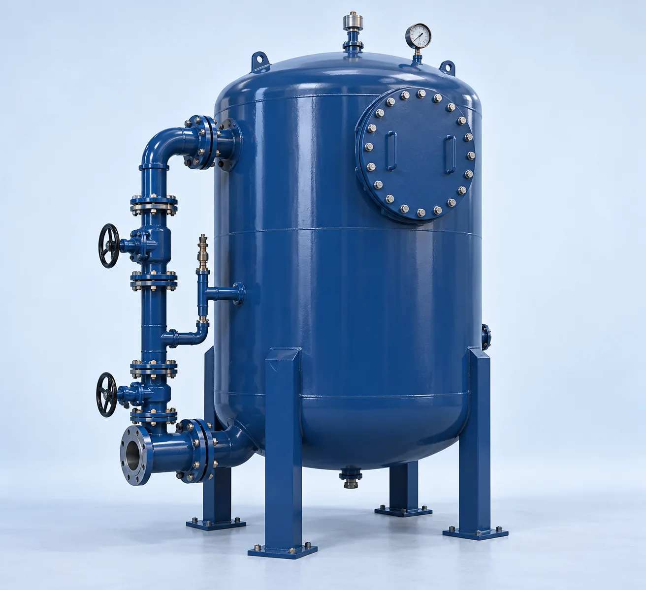
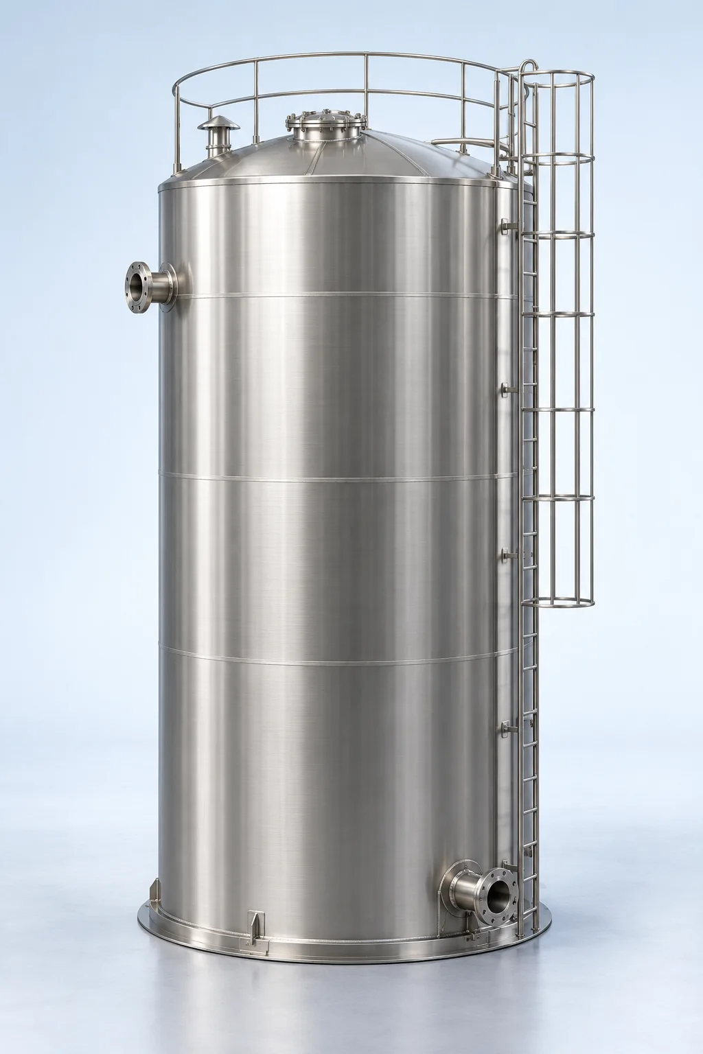
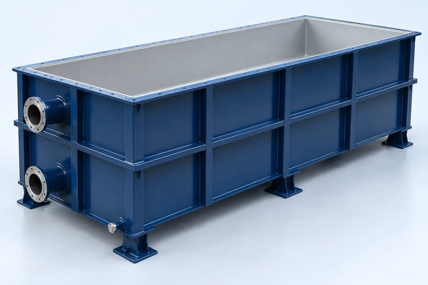
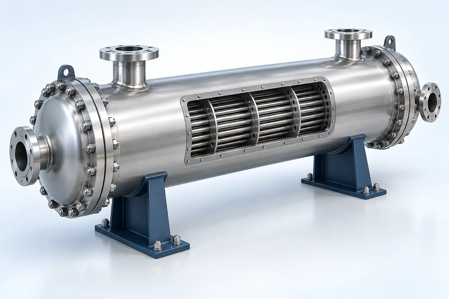
Conceptual 3D visualization of shell-and-tube heat exchanger
Shell-and-tube heat exchanger — conceptual equipment visualization; final configuration follows approved design.

3D EQUIPMENT VIEW

Shell & Tube Heat Exchanger

Explore the equipment arrangement, then read how the system works and review its technical drawings.

Description & drawings Browse equipment renders

Conceptual equipment render. Final dimensions and configuration follow the approved project design.

PRODUCT DESCRIPTION & TECHNICAL DOCUMENTS

How shell & tube heat exchanger fits your process.

Operating principle

Heat transfer between separate shell-side and tube-side fluid circuits through a tube bundle.

One fluid passes through tubes while another passes around the tube bundle. Heat crosses the tube walls; the streams remain physically separated.

Engineering checks

  • Check heat balance and temperature approach
  • Check allowable pressure drop, fouling, thermal expansion and cross-contamination risk
  • Confirm design flow, operating profile and feed properties
  • Agree materials, site interfaces, utilities and maintenance access

Configuration & equipment

  1. Shell
  2. Tube bundle and tube sheets
  3. Channel heads
  4. Baffles
  5. Separate shell-side and tube-side nozzles
  6. Gaskets and supports

Configuration options are reviewed against the project duty. Supply quantities and final scope are defined in the approved proposal.

Process / operating itemEngineering requirement
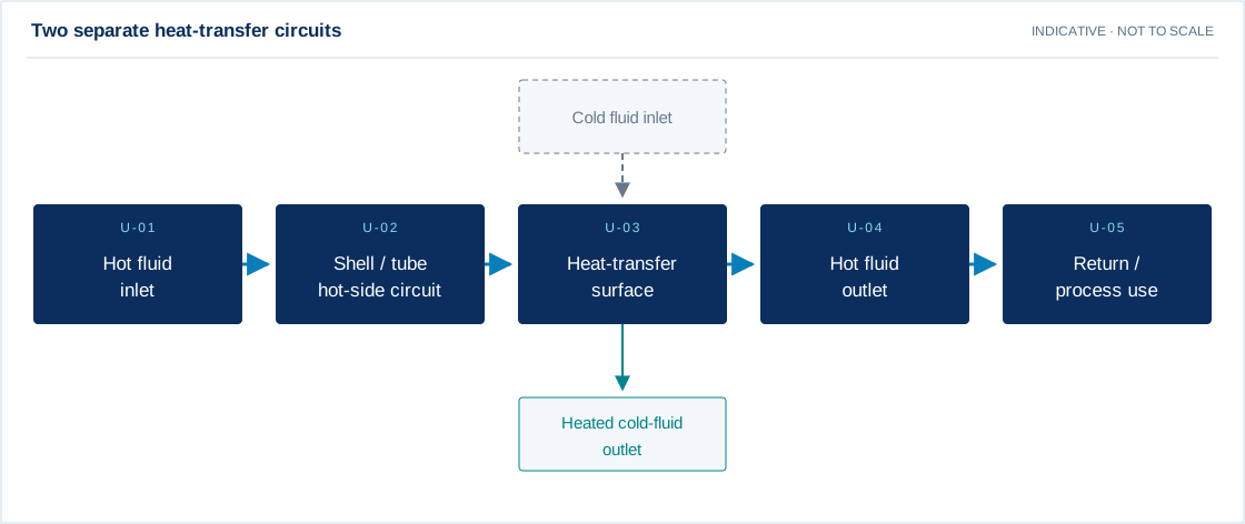
Process review 1Hot and cold fluids remain separate. The middle block represents heat transfer through a wall, not mixing.
Process review 2The allocation of fluids to shell or tube side follows the thermal and mechanical design.
Operating and maintenanceTrend approach temperature and pressure drop. Inspect tubes and clean using the approved method.
DocumentationProject-specific datasheet, PFD, P&ID, equipment GA, electrical load list and O&M documentation as agreed.

PDF & DRAWING DOWNLOADS

Keep the technical references.

Read the process equipment brochure, or download the process and arrangement drawings below.

PROCESS FLOW DIAGRAM

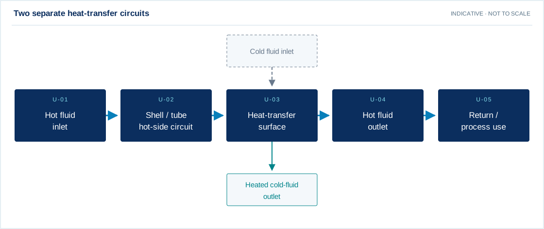
Two separate heat-transfer circuits
Download drawing (SVG)
Hot fluid inlet → Shell / tube hot-side circuit → Heat-transfer surface → Hot fluid outlet → Return / process use
Main process Utility / chemical Residual stream Recovery / recycle

Swipe the diagram to view every stage.

Design notes
  • Hot and cold fluids remain separate. The middle block represents heat transfer through a wall, not mixing.
  • The allocation of fluids to shell or tube side follows the thermal and mechanical design.

Indicative process overview. Equipment tags identify functional blocks only. Final PFDs, P&IDs, duties, sizes, valves and instruments are developed from the approved project design basis.

EQUIPMENT DRAWINGS

2D layout & exploded component views.

Shell & Tube Heat Exchanger 2D functional arrangement
Shell & Tube Heat Exchanger component decomposition reference
Shell & Tube Heat Exchanger — component decomposition

EXPLODED VIEW

Understand the assembly.

  1. Shell
  2. Tube bundle and tube sheets
  3. Channel heads
  4. Baffles
  5. Separate shell-side and tube-side nozzles
  6. Gaskets and supports

EXPLORE YOUR DESIGN BASIS

See how operating hours change energy use.

Enter the total running electrical load for this equipment or plant, then adjust its daily running hours.

Illustrative arithmetic using your inputs. These values are not measured plant results or a performance promise.

Daily electricity
80.00 kWh/day
30-day electricity
2400.00 kWh

Energy = electrical kW × running hours. Constant running load; standby load, starting transients and tariff charges are excluded.

Open detailed calculator →

YOUR PROJECT, YOUR DESIGN BASIS

Configure your requirement.

Enter what you know. Leave unavailable values blank for engineering review.

Process inputs

Both fluids and flow rates, inlet/outlet temperatures, operating/design pressures, fouling, corrosion and allowable pressure drops.

Equipment & execution preferences

Materials are reviewed separately for each component against the fluid chemistry, temperature and service conditions. Preferences are subject to technical suitability and the agreed proposal.

No details are sent until you choose a sending channel.

A solution shaped by your requirements.

Heat transfer between separate shell-side and tube-side fluid circuits through a tube bundle. Process requirements are translated into mechanical design, material selection and fabrication details. Drawings, connections, supports and inspection requirements are agreed before manufacture.

What we review

  • Fluid service, density and chemical compatibility
  • Working volume or design flow
  • Design pressure, vacuum and temperature
  • Material, corrosion allowance and finish
  • Nozzles, supports, loads and site interfaces
  • Applicable design code and inspection requirements

Capacity, materials, operating conditions and performance are specified after review of your project data. Product images are conceptual visualizations.

From design to operation

Our scope can cover process and mechanical engineering, manufacturing, supply, installation, commissioning and ongoing support. The final proposal clearly defines supplier scope, client interfaces, optional items and exclusions.

APPLICATIONS

Connect equipment to your industry.

Review the application, data requirements and candidate treatment options.