
Fabrication & equipment
RO Membrane Pressure Housing
Membrane pressure housings selected for membrane dimensions, operating pressure and service.
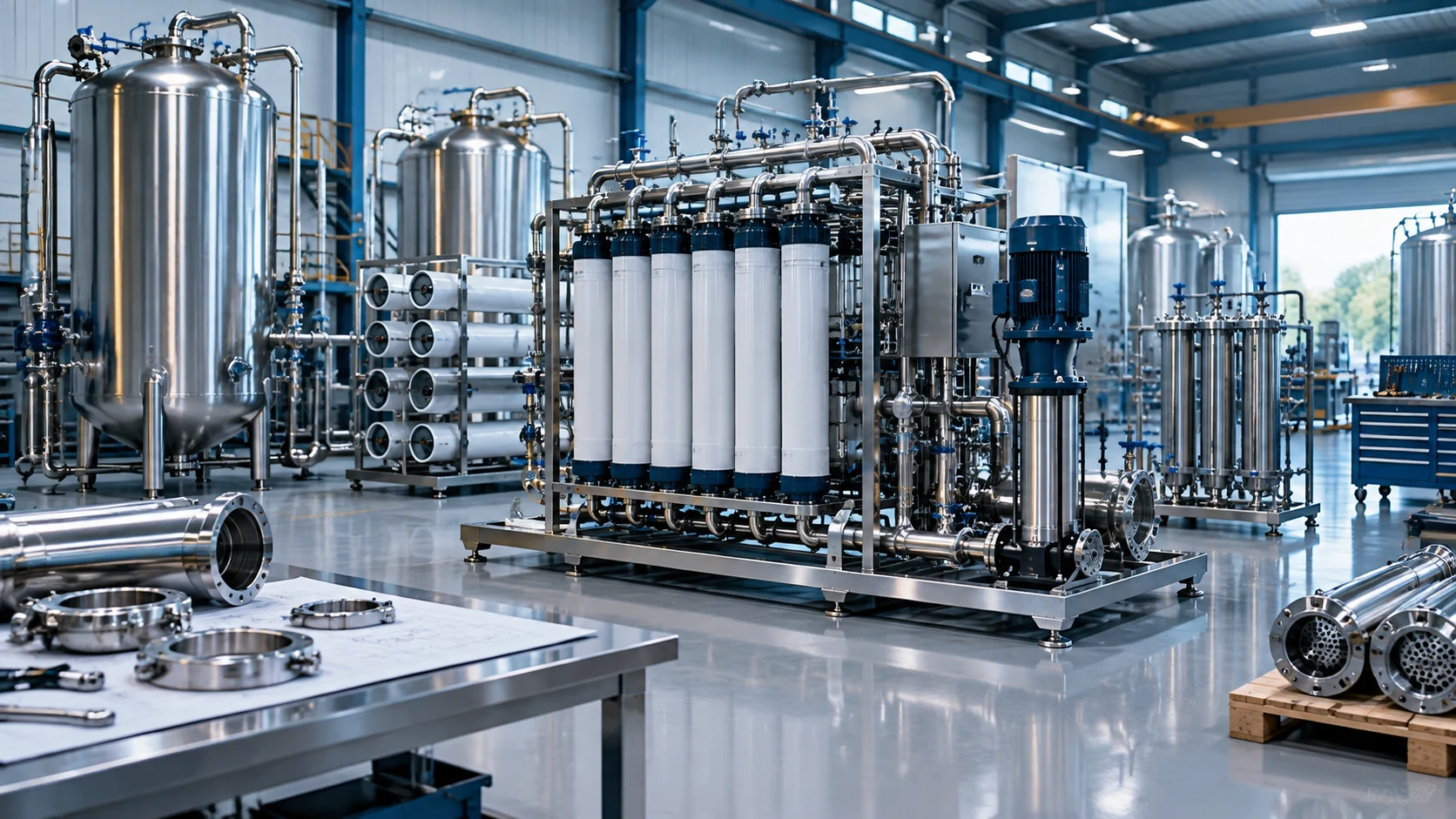
SYSTEM VIEW
See the equipment.
Understand the process.
The render illustrates the Process equipment fabrication equipment family. Your final arrangement follows the project duty, site layout and approved design.
View process flow Browse the visual galleryConceptual 3D visualization · equipment details are illustrative.
PROCESS FLOW DIAGRAM
Reverse osmosis process
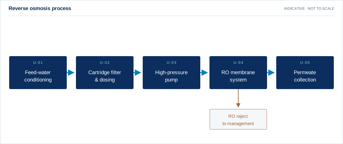
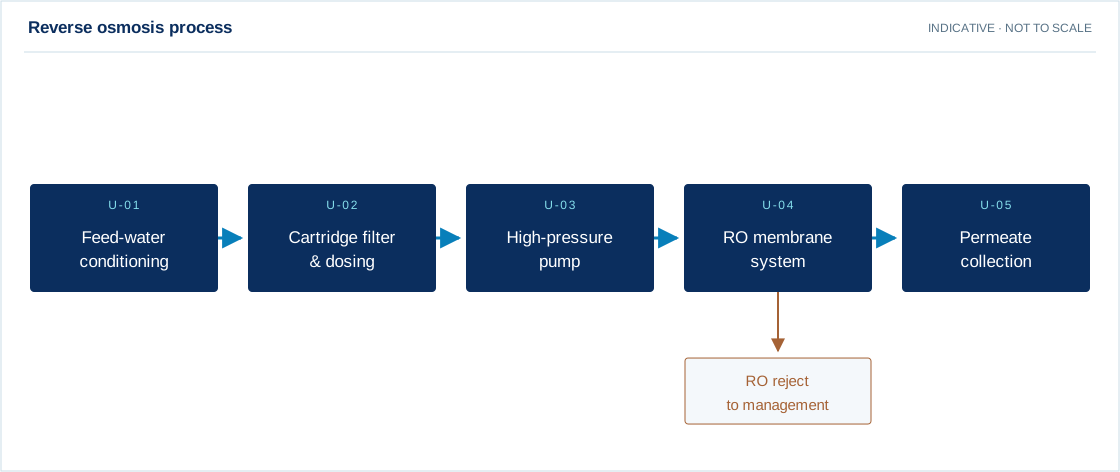
Swipe the diagram to view every stage.
- Pretreatment and chemical dosing depend on the feed-water analysis.
- Reject recovery or disposal, membrane staging and CIP are defined during detailed design.
Indicative process overview. Equipment tags identify functional blocks only. Final PFDs, P&IDs, duties, sizes, valves and instruments are developed from the approved project design basis.
PROCESS & EQUIPMENT DETAILS
How ro membrane pressure housing fits your process.
Operating principle
Membrane pressure housings selected for membrane dimensions, operating pressure and service.
Pressure drives water through a semipermeable membrane. The feed separates into permeate and a concentrate stream; recovery and membrane arrangement are established from water chemistry and a membrane projection.
Engineering checks
- Feed ionic analysis, temperature, SDI and turbidity
- Scaling potential at proposed recovery
- Element flux, crossflow and pressure limits
- Permeate quality and concentrate-management route
Configuration & equipment
- Feed conditioning and cartridge filtration
- High-pressure feed pump
- Membrane pressure housings
- Spiral-wound membrane elements
- Permeate and concentrate manifolds
- Pressure, conductivity and flow instruments
- Cleaning connections and control panel
Configuration options are reviewed against the project duty. Supply quantities and final scope are defined in the approved proposal.
| Process / operating item | Engineering requirement |
|---|---|
| Process review 1 | Pretreatment and chemical dosing depend on the feed-water analysis. |
| Process review 2 | Reject recovery or disposal, membrane staging and CIP are defined during detailed design. |
| Operating and maintenance | Trend normalized permeate flow and salt passage. Inspect differential pressure and cartridge loading. Use approved cleaning chemistry and membrane preservation. |
| Documentation | Project-specific datasheet, PFD, P&ID, equipment GA, electrical load list and O&M documentation as agreed. |
EQUIPMENT DRAWINGS
2D layout & exploded component views.
Review the functional arrangement and the components that make up the equipment.
%22%20stroke%3D%22%230b2e5e%22%20stroke-width%3D%222%22%2F%3E%3Cg%20font-family%3D%22Arial%2CHelvetica%2Csans-serif%22%3E%3Ctext%20x%3D%2246%22%20y%3D%2256%22%20font-size%3D%2217%22%20text-anchor%3D%22start%22%20fill%3D%22%230b2e5e%22%3ERAIN%20POWER%20FILTRATION%3C%2Ftext%3E%3Ctext%20x%3D%221075%22%20y%3D%2256%22%20font-size%3D%2213%22%20text-anchor%3D%22end%22%20fill%3D%22%230b2e5e%22%3EENGINEERING%20REFERENCE%20%C2%B7%20NOT%20TO%20SCALE%3C%2Ftext%3E%3Cpath%20d%3D%22M20%2077H1100%22%20stroke%3D%22%230b2e5e%22%2F%3E%3Ctext%20x%3D%2246%22%20y%3D%22112%22%20font-size%3D%2225%22%20text-anchor%3D%22start%22%20fill%3D%22%230b2e5e%22%3ERO%20Membrane%20Pressure%20Housing%3C%2Ftext%3E%3Ctext%20x%3D%2246%22%20y%3D%22141%22%20font-size%3D%2216%22%20text-anchor%3D%22start%22%20fill%3D%22%230b2e5e%22%3E2D%20functional%20equipment%20arrangement%3C%2Ftext%3E%3Cg%20stroke%3D%22%230b2e5e%22%20stroke-width%3D%222%22%20fill%3D%22none%22%3E%3Crect%20x%3D%22104%22%20y%3D%22200%22%20width%3D%22112%22%20height%3D%2272%22%2F%3E%3Cpath%20d%3D%22M114%2C262%20H206%22%2F%3E%3C%2Fg%3E%3Ccircle%20cx%3D%2277%22%20cy%3D%22218%22%20r%3D%2215%22%20fill%3D%22%230b2e5e%22%2F%3E%3Ctext%20x%3D%2277%22%20y%3D%22223%22%20font-size%3D%2213%22%20text-anchor%3D%22middle%22%20fill%3D%22white%22%3E01%3C%2Ftext%3E%3Ctext%20x%3D%2268%22%20y%3D%22307%22%20font-size%3D%2215%22%20text-anchor%3D%22start%22%20fill%3D%22%230b2e5e%22%3EFeed%20conditioning%20and%3C%2Ftext%3E%3Ctext%20x%3D%2268%22%20y%3D%22327%22%20font-size%3D%2215%22%20text-anchor%3D%22start%22%20fill%3D%22%230b2e5e%22%3Ecartridge%20filtration%3C%2Ftext%3E%3Cpath%20d%3D%22M218%2C236%20H302%22%20stroke%3D%22%23008ab0%22%20stroke-width%3D%222%22%20marker-end%3D%22url(%23arrow)%22%2F%3E%3Cg%20stroke%3D%22%230b2e5e%22%20stroke-width%3D%222%22%20fill%3D%22none%22%3E%3Ccircle%20cx%3D%22426%22%20cy%3D%22236%22%20r%3D%2236%22%2F%3E%3Cpath%20d%3D%22M402%2C209%20L454%2C236%20L402%2C263Z%22%2F%3E%3C%2Fg%3E%3Ccircle%20cx%3D%22343%22%20cy%3D%22218%22%20r%3D%2215%22%20fill%3D%22%230b2e5e%22%2F%3E%3Ctext%20x%3D%22343%22%20y%3D%22223%22%20font-size%3D%2213%22%20text-anchor%3D%22middle%22%20fill%3D%22white%22%3E02%3C%2Ftext%3E%3Ctext%20x%3D%22334%22%20y%3D%22307%22%20font-size%3D%2215%22%20text-anchor%3D%22start%22%20fill%3D%22%230b2e5e%22%3EHigh-pressure%20feed%20pump%3C%2Ftext%3E%3Cpath%20d%3D%22M484%2C236%20H568%22%20stroke%3D%22%23008ab0%22%20stroke-width%3D%222%22%20marker-end%3D%22url(%23arrow)%22%2F%3E%3Cg%20stroke%3D%22%230b2e5e%22%20stroke-width%3D%222%22%20fill%3D%22none%22%3E%3Cpath%20d%3D%22M636%2C213%20Q692%2C191%20748%2C213%20V259%20Q692%2C281%20636%2C259Z%20M636%2C213%20Q692%2C235%20748%2C213%22%2F%3E%3C%2Fg%3E%3Ccircle%20cx%3D%22609%22%20cy%3D%22218%22%20r%3D%2215%22%20fill%3D%22%230b2e5e%22%2F%3E%3Ctext%20x%3D%22609%22%20y%3D%22223%22%20font-size%3D%2213%22%20text-anchor%3D%22middle%22%20fill%3D%22white%22%3E03%3C%2Ftext%3E%3Ctext%20x%3D%22600%22%20y%3D%22307%22%20font-size%3D%2215%22%20text-anchor%3D%22start%22%20fill%3D%22%230b2e5e%22%3EMembrane%20pressure%20housings%3C%2Ftext%3E%3Cpath%20d%3D%22M750%2C236%20H834%22%20stroke%3D%22%23008ab0%22%20stroke-width%3D%222%22%20marker-end%3D%22url(%23arrow)%22%2F%3E%3Cg%20stroke%3D%22%230b2e5e%22%20stroke-width%3D%222%22%20fill%3D%22none%22%3E%3Crect%20x%3D%22902%22%20y%3D%22200%22%20width%3D%22112%22%20height%3D%2272%22%2F%3E%3Cpath%20d%3D%22M924.4%2C200%20V272%22%2F%3E%3Cpath%20d%3D%22M946.8%2C200%20V272%22%2F%3E%3Cpath%20d%3D%22M969.2%2C200%20V272%22%2F%3E%3Cpath%20d%3D%22M991.6%2C200%20V272%22%2F%3E%3C%2Fg%3E%3Ccircle%20cx%3D%22875%22%20cy%3D%22218%22%20r%3D%2215%22%20fill%3D%22%230b2e5e%22%2F%3E%3Ctext%20x%3D%22875%22%20y%3D%22223%22%20font-size%3D%2213%22%20text-anchor%3D%22middle%22%20fill%3D%22white%22%3E04%3C%2Ftext%3E%3Ctext%20x%3D%22866%22%20y%3D%22307%22%20font-size%3D%2215%22%20text-anchor%3D%22start%22%20fill%3D%22%230b2e5e%22%3ESpiral-wound%20membrane%3C%2Ftext%3E%3Ctext%20x%3D%22866%22%20y%3D%22327%22%20font-size%3D%2215%22%20text-anchor%3D%22start%22%20fill%3D%22%230b2e5e%22%3Eelements%3C%2Ftext%3E%3Cg%20stroke%3D%22%230b2e5e%22%20stroke-width%3D%222%22%20fill%3D%22none%22%3E%3Crect%20x%3D%22104%22%20y%3D%22402%22%20width%3D%22112%22%20height%3D%2272%22%2F%3E%3Cpath%20d%3D%22M114%2C464%20H206%22%2F%3E%3C%2Fg%3E%3Ccircle%20cx%3D%2277%22%20cy%3D%22420%22%20r%3D%2215%22%20fill%3D%22%230b2e5e%22%2F%3E%3Ctext%20x%3D%2277%22%20y%3D%22425%22%20font-size%3D%2213%22%20text-anchor%3D%22middle%22%20fill%3D%22white%22%3E05%3C%2Ftext%3E%3Ctext%20x%3D%2268%22%20y%3D%22509%22%20font-size%3D%2215%22%20text-anchor%3D%22start%22%20fill%3D%22%230b2e5e%22%3EPermeate%20and%20concentrate%3C%2Ftext%3E%3Ctext%20x%3D%2268%22%20y%3D%22529%22%20font-size%3D%2215%22%20text-anchor%3D%22start%22%20fill%3D%22%230b2e5e%22%3Emanifolds%3C%2Ftext%3E%3Cpath%20d%3D%22M218%2C438%20H302%22%20stroke%3D%22%23008ab0%22%20stroke-width%3D%222%22%20marker-end%3D%22url(%23arrow)%22%2F%3E%3Cg%20stroke%3D%22%230b2e5e%22%20stroke-width%3D%222%22%20fill%3D%22none%22%3E%3Crect%20x%3D%22370%22%20y%3D%22402%22%20width%3D%22112%22%20height%3D%2272%22%2F%3E%3Cpath%20d%3D%22M380%2C464%20H472%22%2F%3E%3C%2Fg%3E%3Ccircle%20cx%3D%22343%22%20cy%3D%22420%22%20r%3D%2215%22%20fill%3D%22%230b2e5e%22%2F%3E%3Ctext%20x%3D%22343%22%20y%3D%22425%22%20font-size%3D%2213%22%20text-anchor%3D%22middle%22%20fill%3D%22white%22%3E06%3C%2Ftext%3E%3Ctext%20x%3D%22334%22%20y%3D%22509%22%20font-size%3D%2215%22%20text-anchor%3D%22start%22%20fill%3D%22%230b2e5e%22%3EPressure%2C%20conductivity%20and%3C%2Ftext%3E%3Ctext%20x%3D%22334%22%20y%3D%22529%22%20font-size%3D%2215%22%20text-anchor%3D%22start%22%20fill%3D%22%230b2e5e%22%3Eflow%20instruments%3C%2Ftext%3E%3Cpath%20d%3D%22M484%2C438%20H568%22%20stroke%3D%22%23008ab0%22%20stroke-width%3D%222%22%20marker-end%3D%22url(%23arrow)%22%2F%3E%3Cg%20stroke%3D%22%230b2e5e%22%20stroke-width%3D%222%22%20fill%3D%22none%22%3E%3Crect%20x%3D%22636%22%20y%3D%22402%22%20width%3D%22112%22%20height%3D%2272%22%2F%3E%3Cpath%20d%3D%22M646%2C464%20H738%22%2F%3E%3C%2Fg%3E%3Ccircle%20cx%3D%22609%22%20cy%3D%22420%22%20r%3D%2215%22%20fill%3D%22%230b2e5e%22%2F%3E%3Ctext%20x%3D%22609%22%20y%3D%22425%22%20font-size%3D%2213%22%20text-anchor%3D%22middle%22%20fill%3D%22white%22%3E07%3C%2Ftext%3E%3Ctext%20x%3D%22600%22%20y%3D%22509%22%20font-size%3D%2215%22%20text-anchor%3D%22start%22%20fill%3D%22%230b2e5e%22%3ECleaning%20connections%20and%3C%2Ftext%3E%3Ctext%20x%3D%22600%22%20y%3D%22529%22%20font-size%3D%2215%22%20text-anchor%3D%22start%22%20fill%3D%22%230b2e5e%22%3Econtrol%20panel%3C%2Ftext%3E%3Ctext%20x%3D%2258%22%20y%3D%22612%22%20font-size%3D%2215%22%20text-anchor%3D%22start%22%20fill%3D%22%230b2e5e%22%3ESymbols%20locate%20functional%20equipment%20groups%3B%20flow%20connections%20follow%20the%20PFD.%3C%2Ftext%3E%3Cpath%20d%3D%22M20%20635H1100%20M750%20635V760%20M930%20635V760%22%20stroke%3D%22%230b2e5e%22%2F%3E%3Ctext%20x%3D%2245%22%20y%3D%22665%22%20font-size%3D%2213%22%20text-anchor%3D%22start%22%20fill%3D%22%230b2e5e%22%3EDRAWING%20BASIS%3C%2Ftext%3E%3Ctext%20x%3D%2245%22%20y%3D%22690%22%20font-size%3D%2216%22%20text-anchor%3D%22start%22%20fill%3D%22%230b2e5e%22%3EEquipment-family%20reference.%20Final%20layout%2C%20quantities%2C%20materials%2C%3C%2Ftext%3E%3Ctext%20x%3D%2245%22%20y%3D%22712%22%20font-size%3D%2216%22%20text-anchor%3D%22start%22%20fill%3D%22%230b2e5e%22%3Edimensions%2C%20nozzles%20and%20maintenance%20clearances%20require%20approval.%3C%2Ftext%3E%3Ctext%20x%3D%2245%22%20y%3D%22741%22%20font-size%3D%2214%22%20text-anchor%3D%22start%22%20fill%3D%22%230b2e5e%22%3EUse%20the%20approved%20project%20GA%20and%20vendor%20drawings%20for%20construction.%3C%2Ftext%3E%3Ctext%20x%3D%22773%22%20y%3D%22664%22%20font-size%3D%2212%22%20text-anchor%3D%22start%22%20fill%3D%22%230b2e5e%22%3EVIEW%3C%2Ftext%3E%3Ctext%20x%3D%22773%22%20y%3D%22692%22%20font-size%3D%2217%22%20text-anchor%3D%22start%22%20fill%3D%22%230b2e5e%22%3ELAYOUT%3C%2Ftext%3E%3Ctext%20x%3D%22773%22%20y%3D%22732%22%20font-size%3D%2212%22%20text-anchor%3D%22start%22%20fill%3D%22%230b2e5e%22%3ESTATUS%3A%20REFERENCE%3C%2Ftext%3E%3Ctext%20x%3D%22952%22%20y%3D%22664%22%20font-size%3D%2212%22%20text-anchor%3D%22start%22%20fill%3D%22%230b2e5e%22%3ESCALE%3C%2Ftext%3E%3Ctext%20x%3D%22952%22%20y%3D%22692%22%20font-size%3D%2218%22%20text-anchor%3D%22start%22%20fill%3D%22%230b2e5e%22%3ENTS%3C%2Ftext%3E%3Ctext%20x%3D%22952%22%20y%3D%22732%22%20font-size%3D%2212%22%20text-anchor%3D%22start%22%20fill%3D%22%230b2e5e%22%3EUNITS%3A%20SI%3C%2Ftext%3E%3C%2Fg%3E%3C%2Fsvg%3E)
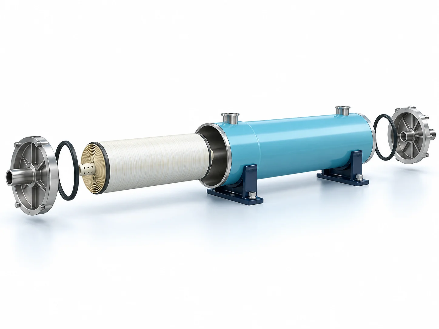
EXPLODED VIEW
Understand the assembly.
Illustrative spiral-wound membrane assembly. Element count, closure design and connections depend on the selected housing.
- Feed conditioning and cartridge filtration
- High-pressure feed pump
- Membrane pressure housings
- Spiral-wound membrane elements
- Permeate and concentrate manifolds
- Pressure, conductivity and flow instruments
- Cleaning connections and control panel
YOUR PROJECT, YOUR DESIGN BASIS
Configure your requirement.
Enter what you know. Leave unavailable values blank for engineering review.
A solution shaped by your requirements.
Membrane pressure housings selected for membrane dimensions, operating pressure and service. Process requirements are translated into mechanical design, material selection and fabrication details. Drawings, connections, supports and inspection requirements are agreed before manufacture.
What we review
- Fluid service, density and chemical compatibility
- Working volume or design flow
- Design pressure, vacuum and temperature
- Material, corrosion allowance and finish
- Nozzles, supports, loads and site interfaces
- Applicable design code and inspection requirements
Capacity, materials, operating conditions and performance are specified after review of your project data. Product images are conceptual visualizations.
From design to operation
Our scope can cover process and mechanical engineering, manufacturing, supply, installation, commissioning and ongoing support. The final proposal clearly defines supplier scope, client interfaces, optional items and exclusions.
APPLICATIONS
Connect equipment to your industry.
Review the application, data requirements and candidate treatment options.
EXPLORE FURTHER
Related solutions
3D system familyPressure Filtration Vessel
Fabricated pressure filtration vessels to an agreed design basis and applicable design code.
Explore3D system familyVertical Storage Tank
Vertical storage vessels selected for fluid properties, site constraints and loading conditions.
Explore3D system familyRectangular Process Tank
Rectangular process tanks with project-specific working volume and structural design.
Explore