PRODUCT DESCRIPTION & TECHNICAL DOCUMENTS
How ozone disinfection system fits your process.
Operating principle
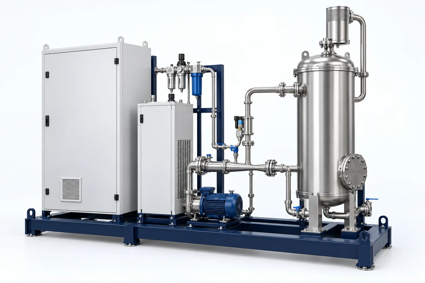
Ozone generation and contacting for application-specific oxidation and disinfection duties.
Disinfection or oxidation performance depends on contact conditions and water quality. UV uses a validated reactor and exposure dose; ozone or advanced oxidation requires an approved chemical and safety design.
Engineering checks
- Water quality and treatment objective
- Validated dose or treatability test basis
- Required contact and reaction conditions
- Interlocks, residual control and operator protection
Configuration & equipment
- Feed-quality and flow interface
- Reactor / contact assembly
- Selected energy or oxidant source
- Monitoring and control system
- Residual / off-gas handling where applicable
- Outlet sampling point
Configuration options are reviewed against the project duty. Supply quantities and final scope are defined in the approved proposal.
| Process / operating item | Engineering requirement |
|---|---|
| Process review 1 | Oxidation chemistry, by-products and final polishing depend on treatability testing. |
| Process review 2 | Ozone applications require appropriate off-gas destruction and safety provisions. |
| Operating and maintenance | Inspect the reactor and clean fouled surfaces. Verify sensors and safety interlocks. Replace consumables according to selected equipment instructions. |
| Documentation | Project-specific datasheet, PFD, P&ID, equipment GA, electrical load list and O&M documentation as agreed. |
PDF & DRAWING DOWNLOADS
Keep the technical references.
Read the water treatment & ro brochure, or download the process and arrangement drawings below.
PROCESS FLOW DIAGRAM
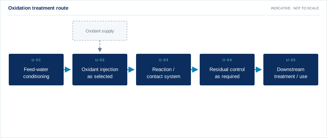
Oxidation treatment route
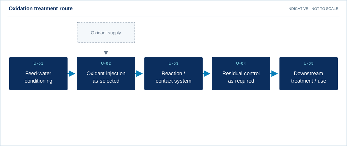
Swipe the diagram to view every stage.
- Oxidation chemistry, by-products and final polishing depend on treatability testing.
- Ozone applications require appropriate off-gas destruction and safety provisions.
Indicative process overview. Equipment tags identify functional blocks only. Final PFDs, P&IDs, duties, sizes, valves and instruments are developed from the approved project design basis.
EQUIPMENT DRAWINGS
2D layout & exploded component views.
Review the functional arrangement and the components that make up the equipment.


EXPLODED VIEW
Understand the assembly.
The separated component schematic identifies the main equipment groups. Vendor-specific internal geometry is established during detailed engineering.
- Feed-quality and flow interface
- Reactor / contact assembly
- Selected energy or oxidant source
- Monitoring and control system
- Residual / off-gas handling where applicable
- Outlet sampling point