PRODUCT DESCRIPTION & TECHNICAL DOCUMENTS
How industrial mixing tank fits your process.
Operating principle
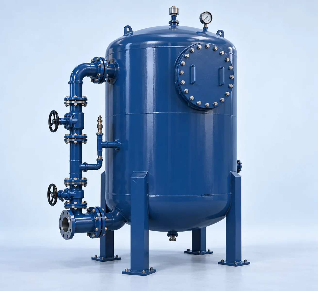
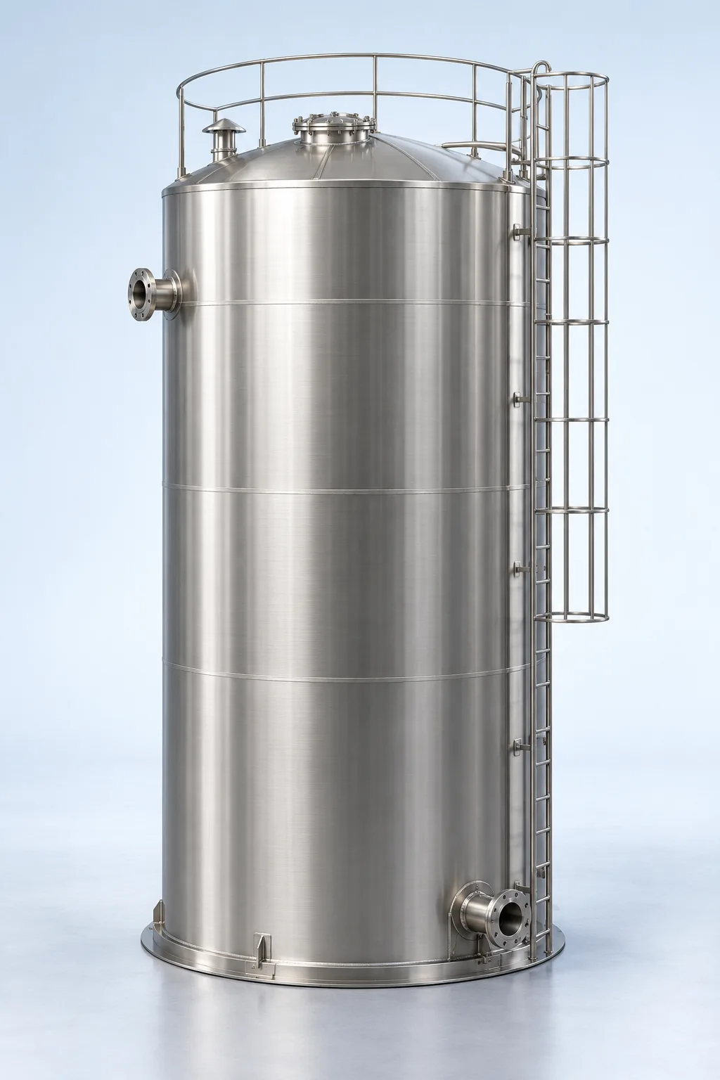
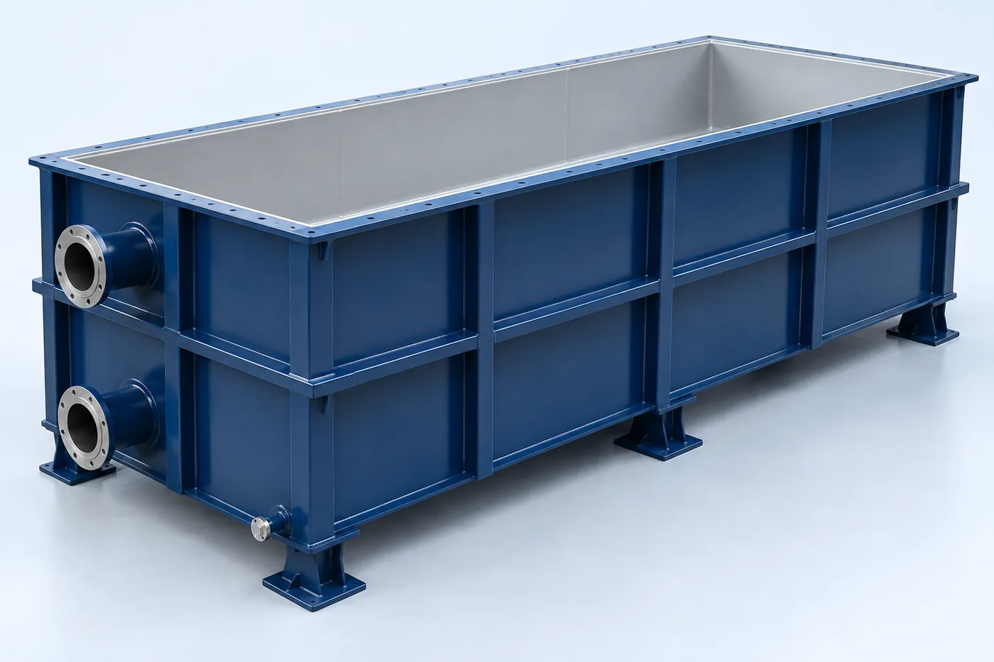
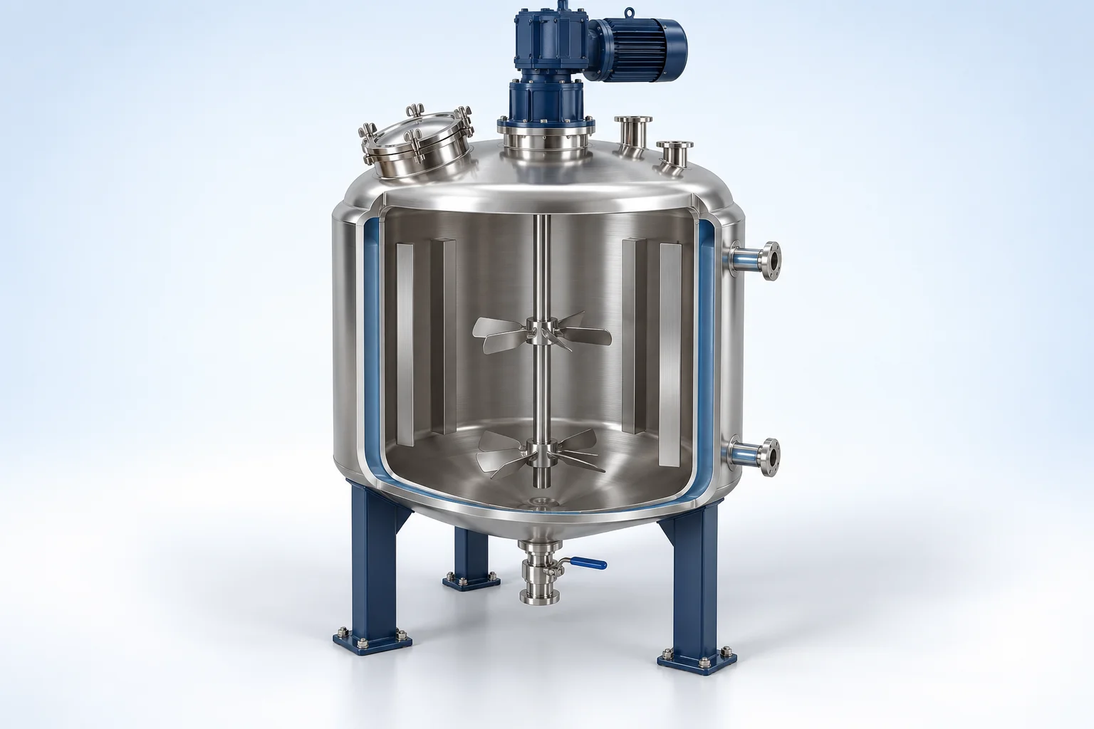
An agitated tank for liquid blending, dissolution or suspension, with optional thermal control for the selected process.
An impeller transfers momentum to the liquid for blending, dissolution or suspension. Impeller geometry, baffles and speed depend on viscosity, density and the mixing objective.
Engineering checks
- Review mixing trials, rheology, settling and shear sensitivity
- Check shaft loads and any thermal-control duty
- Confirm design flow, operating profile and feed properties
- Agree materials, site interfaces, utilities and maintenance access
Configuration & equipment
- Process tank
- Agitator and drive
- Impeller
- Baffles where required
- Inlet and discharge connections
- Optional jacket / coil
Configuration options are reviewed against the project duty. Supply quantities and final scope are defined in the approved proposal.
| Process / operating item | Engineering requirement |
|---|---|
| Process review 1 | Impeller, baffles, speed and thermal control depend on mixing duty and fluid properties. |
| Operating and maintenance | Inspect shaft, seals and drive. Check mixing performance at intended fill levels. |
| Documentation | Project-specific datasheet, PFD, P&ID, equipment GA, electrical load list and O&M documentation as agreed. |
PDF & DRAWING DOWNLOADS
Keep the technical references.
Read the process equipment brochure, or download the process and arrangement drawings below.
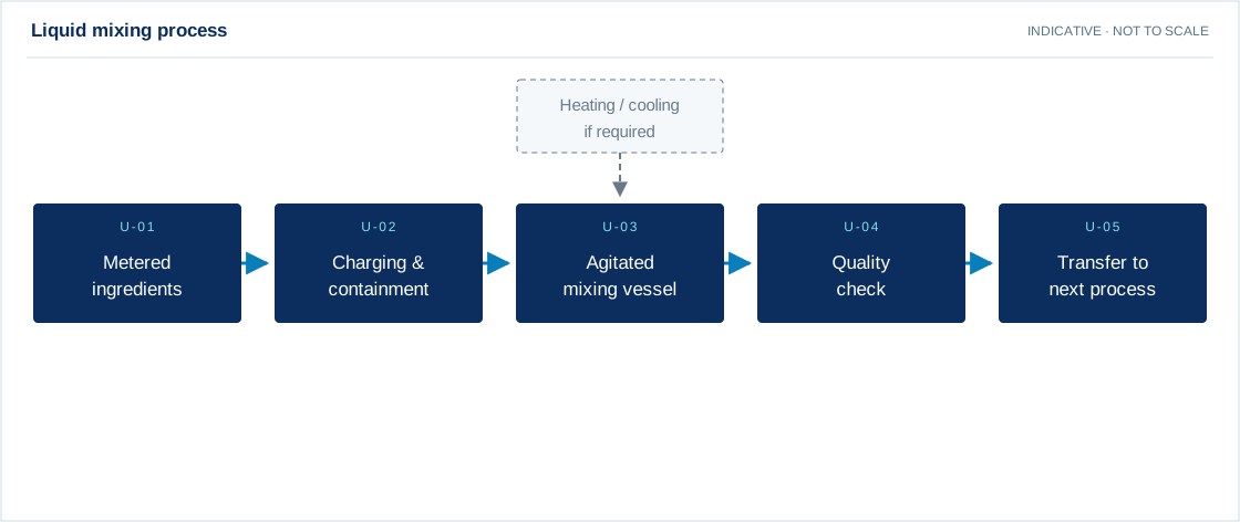
PROCESS FLOW DIAGRAM
Liquid mixing process
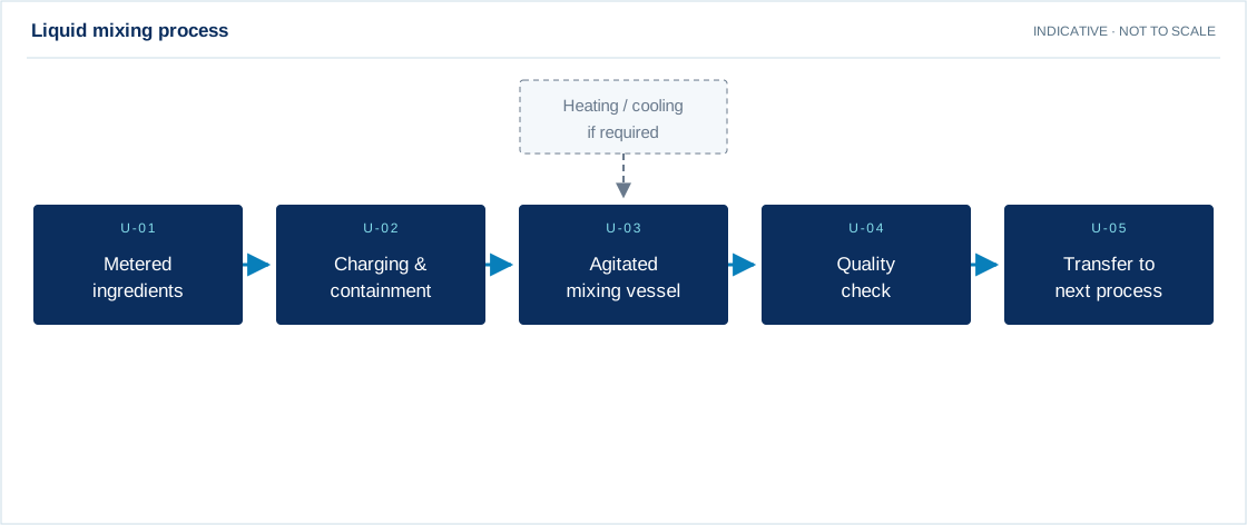
Swipe the diagram to view every stage.
- Impeller, baffles, speed and thermal control depend on mixing duty and fluid properties.
Indicative process overview. Equipment tags identify functional blocks only. Final PFDs, P&IDs, duties, sizes, valves and instruments are developed from the approved project design basis.
EQUIPMENT DRAWINGS
2D layout & exploded component views.
Review the functional arrangement and the components that make up the equipment.


EXPLODED VIEW
Understand the assembly.
The separated component schematic identifies the main equipment groups. Vendor-specific internal geometry is established during detailed engineering.
- Process tank
- Agitator and drive
- Impeller
- Baffles where required
- Inlet and discharge connections
- Optional jacket / coil