PRODUCT DESCRIPTION & TECHNICAL DOCUMENTS
How industrial evaporator fits your process.
Operating principle
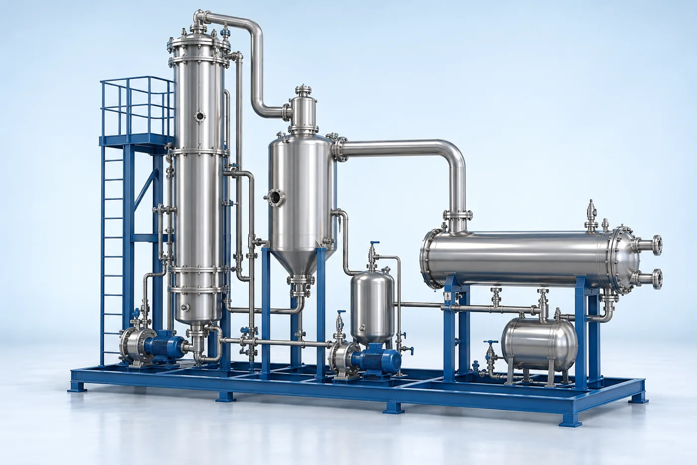
Evaporation equipment configured around feed properties, concentration duty and available utilities.
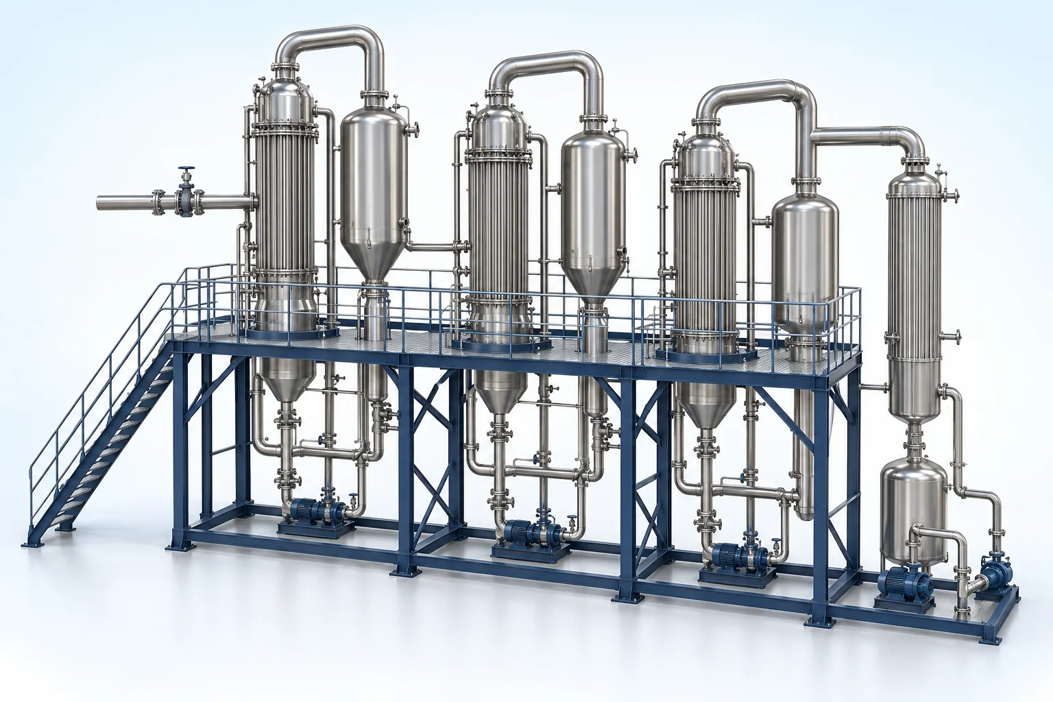
Thermal concentration removes water by evaporation and increases nonvolatile solids concentration. MEE, MVR, crystallization and ATFD use different heat-transfer and solids-handling arrangements.
Engineering checks
- Feed mass flow and full salt chemistry
- Boiling-point elevation, fouling and corrosion
- Heat and mass balance with utility basis
- Condensate quality and final solids route
Configuration & equipment
- Conditioned concentrate feed
- Heating surface / heat exchanger
- Evaporation or drying chamber
- Vapour separation and handling
- Condensation / heat-recovery interface
- Concentrate or solids discharge
- Cleaning and control system
Configuration options are reviewed against the project duty. Supply quantities and final scope are defined in the approved proposal.
| Process / operating item | Engineering requirement |
|---|---|
| Process review 1 | Heat supply, number of effects or vapor recompression are selected during thermal design. |
| Process review 2 | Condensate reuse depends on analysis, polishing and the intended duty. |
| Operating and maintenance | Trend heat transfer and fouling indicators. Inspect seals, vacuum and vapour systems. Follow approved descaling and shutdown procedures. |
| Documentation | Project-specific datasheet, PFD, P&ID, equipment GA, electrical load list and O&M documentation as agreed. |
PDF & DRAWING DOWNLOADS
Keep the technical references.
Read the zld & recovery brochure, or download the process and arrangement drawings below.
PROCESS FLOW DIAGRAM
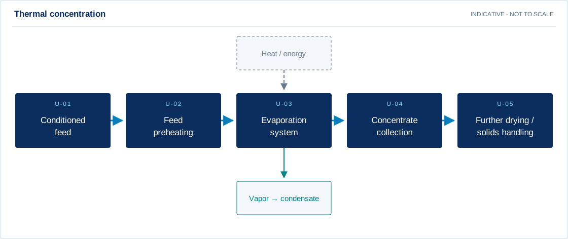
Thermal concentration
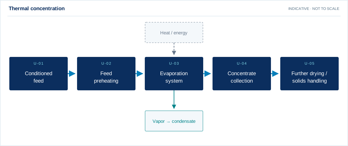
Swipe the diagram to view every stage.
- Heat supply, number of effects or vapor recompression are selected during thermal design.
- Condensate reuse depends on analysis, polishing and the intended duty.
Indicative process overview. Equipment tags identify functional blocks only. Final PFDs, P&IDs, duties, sizes, valves and instruments are developed from the approved project design basis.
EQUIPMENT DRAWINGS
2D layout & exploded component views.
Review the functional arrangement and the components that make up the equipment.


EXPLODED VIEW
Understand the assembly.
The separated component schematic identifies the main equipment groups. Vendor-specific internal geometry is established during detailed engineering.
- Conditioned concentrate feed
- Heating surface / heat exchanger
- Evaporation or drying chamber
- Vapour separation and handling
- Condensation / heat-recovery interface
- Concentrate or solids discharge
- Cleaning and control system