Bakrol, Ahmedabad, India+91 97277 86892

Fabrication & equipment

Industrial Cooling Tower

Evaporative heat rejection from circulating water to ambient air for suitable industrial cooling-water duties.

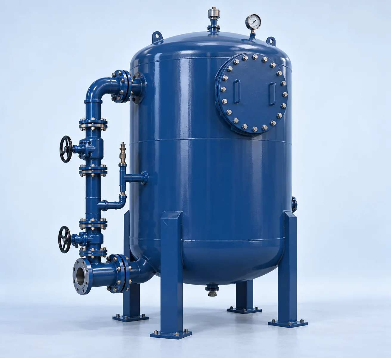
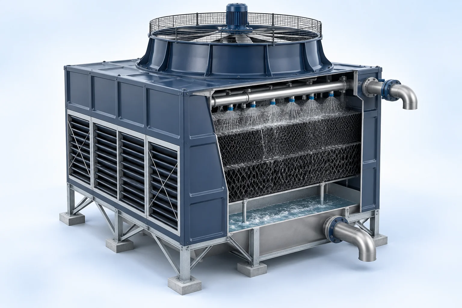
Conceptual 3D visualization of counterflow cooling tower
Counterflow cooling tower — conceptual equipment visualization; final configuration follows approved design.

3D EQUIPMENT VIEW

Industrial Cooling Tower

Explore the equipment arrangement, then read how the system works and review its technical drawings.

Description & drawings Browse equipment renders

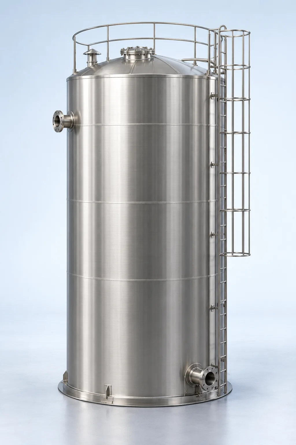
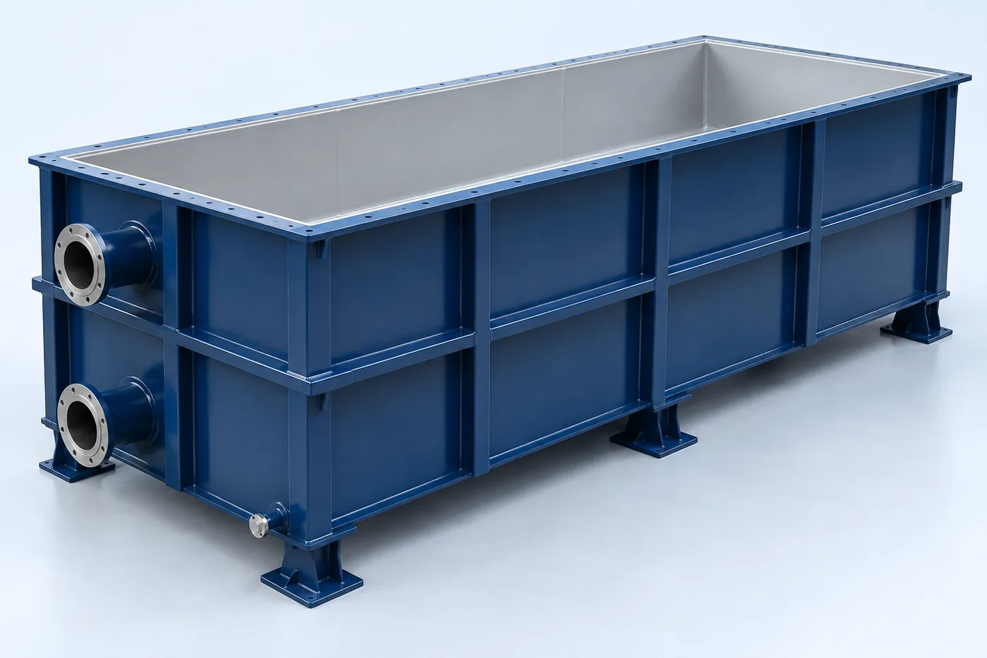
Conceptual equipment render. Final dimensions and configuration follow the approved project design.

PRODUCT DESCRIPTION & TECHNICAL DOCUMENTS

How industrial cooling tower fits your process.

Operating principle

Evaporative heat rejection from circulating water to ambient air for suitable industrial cooling-water duties.

Warm circulating water contacts moving air across fill. Evaporation removes heat. Makeup replaces evaporation, drift and controlled blowdown. Cooling potential depends on the ambient wet-bulb temperature.

Engineering checks

  • Use site design wet-bulb, range and approach
  • Review water treatment, drift, biological control and noise
  • Confirm design flow, operating profile and feed properties
  • Agree materials, site interfaces, utilities and maintenance access

Configuration & equipment

  1. Water distribution system
  2. Fill pack
  3. Fan and drive
  4. Drift eliminators
  5. Cold-water basin
  6. Makeup and blowdown connections

Configuration options are reviewed against the project duty. Supply quantities and final scope are defined in the approved proposal.

Process / operating itemEngineering requirement
Process review 1Evaporation, drift and controlled blowdown require makeup water.
Process review 2Design wet-bulb temperature, approach and range determine performance.
Operating and maintenanceInspect fill, eliminators and fan. Maintain the agreed water-treatment and hygiene programme.
DocumentationProject-specific datasheet, PFD, P&ID, equipment GA, electrical load list and O&M documentation as agreed.

PDF & DRAWING DOWNLOADS

Keep the technical references.

Read the process equipment brochure, or download the process and arrangement drawings below.

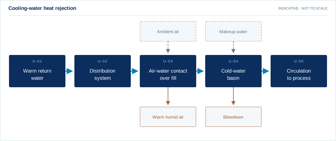
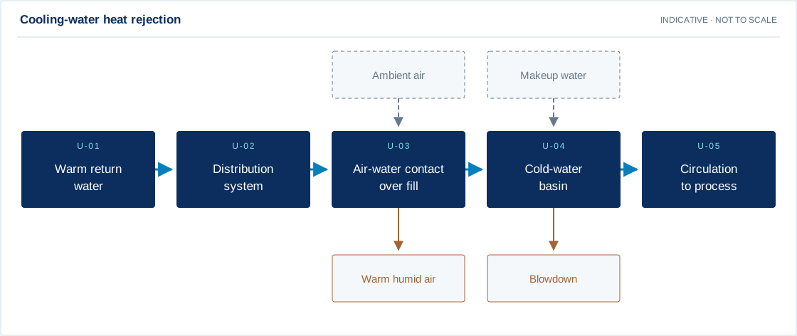
PROCESS FLOW DIAGRAM

Cooling-water heat rejection
Download drawing (SVG)
Warm return water → Distribution system → Air-water contact over fill → Cold-water basin → Circulation to process
Main process Utility / chemical Residual stream Recovery / recycle

Swipe the diagram to view every stage.

Design notes
  • Evaporation, drift and controlled blowdown require makeup water.
  • Design wet-bulb temperature, approach and range determine performance.

Indicative process overview. Equipment tags identify functional blocks only. Final PFDs, P&IDs, duties, sizes, valves and instruments are developed from the approved project design basis.

EQUIPMENT DRAWINGS

2D layout & exploded component views.

Industrial Cooling Tower 2D functional arrangement
Industrial Cooling Tower component decomposition reference
Industrial Cooling Tower — component decomposition

EXPLODED VIEW

Understand the assembly.

  1. Water distribution system
  2. Fill pack
  3. Fan and drive
  4. Drift eliminators
  5. Cold-water basin
  6. Makeup and blowdown connections

EXPLORE YOUR DESIGN BASIS

See how operating hours change energy use.

Enter the total running electrical load for this equipment or plant, then adjust its daily running hours.

Illustrative arithmetic using your inputs. These values are not measured plant results or a performance promise.

Daily electricity
80.00 kWh/day
30-day electricity
2400.00 kWh

Energy = electrical kW × running hours. Constant running load; standby load, starting transients and tariff charges are excluded.

Open detailed calculator →

YOUR PROJECT, YOUR DESIGN BASIS

Configure your requirement.

Enter what you know. Leave unavailable values blank for engineering review.

Process inputs

Water flow, hot/cold water temperatures, site design wet-bulb, water chemistry, cycles, noise and footprint.

Equipment & execution preferences

Materials are reviewed separately for each component against the fluid chemistry, temperature and service conditions. Preferences are subject to technical suitability and the agreed proposal.

No details are sent until you choose a sending channel.

A solution shaped by your requirements.

Evaporative heat rejection from circulating water to ambient air for suitable industrial cooling-water duties. Process requirements are translated into mechanical design, material selection and fabrication details. Drawings, connections, supports and inspection requirements are agreed before manufacture.

What we review

  • Fluid service, density and chemical compatibility
  • Working volume or design flow
  • Design pressure, vacuum and temperature
  • Material, corrosion allowance and finish
  • Nozzles, supports, loads and site interfaces
  • Applicable design code and inspection requirements

Capacity, materials, operating conditions and performance are specified after review of your project data. Product images are conceptual visualizations.

From design to operation

Our scope can cover process and mechanical engineering, manufacturing, supply, installation, commissioning and ongoing support. The final proposal clearly defines supplier scope, client interfaces, optional items and exclusions.

APPLICATIONS

Connect equipment to your industry.

Review the application, data requirements and candidate treatment options.